
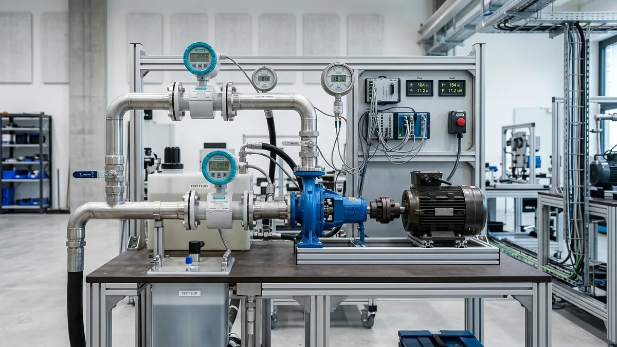
Total Head Calculation for Chemical Process Pumps: Static Lift, Darcy-Weisbach Friction & Hydraulic Sizing Engineering Standard
A definitive hydraulic head calculation manual, pipe friction loss engineering standard, and pump sizing guide for chemical process engineers, plant design consultants, and utility piping superintendents across Ahmedabad, Vatva, Ankleshwar, Dahej, and Gujarat.
Quick Answer
In chemical manufacturing plants, pharmaceutical bulk active synthesis corridors, and petrochemical utility complexes across Gujarat—spanning Ahmedabad (Vatva, Naroda, Odhav), Ankleshwar GIDC, Dahej PCPIR, and Vapi—centrifugal process pumps transfer hazardous, corrosive, and viscous liquids across complex piping networks, elevated scrubbers, pressurized reactors, and heat exchangers. Inaccurate total head calculations cause immediate plant bottlenecks: under-estimating total dynamic head (TDH) results in flow starvation where the pump fails to reach the destination vessel, while over-estimating head causes the pump to operate far to the right of its best efficiency point (BEP), triggering severe motor overload and cavitation. Calculating exact total dynamic head requires summing four hydraulic components: static elevation head (ΔZ = Z_d - Z_s), surface pressure differential head (ΔH_press = [P_d - P_s] / [ρ· g]), pipe wall friction head loss using the Darcy-Weisbach equation (h_f = f · (L) / (D) · [v²] / [2g]), and minor fitting and valve resistance losses (\Sigma K · [v²] / [2g]). Sizing chemical pumps conforming to ISO 5199, ISO 2858, IS 5120, and IS 1520 standards with engineered PTFE/PFA lined wet ends guarantees stable hydraulic performance and eliminates motor tripping.
Key Takeaways
- Calculate the 4 Components of Total Dynamic Head (TDH). Sum static elevation, vessel surface pressure differential, pipe friction, and fitting losses.
- Apply the Darcy-Weisbach Friction Equation for Exact Head Loss. Avoid rough Hazen-Williams estimates on non-water and viscous chemical process fluids.
- Incorporate Equivalent Lengths (L_e) or K-Factors for Fittings. Valves, elbows, strainers, and flow meters contribute up to 40% of total friction head.
- Derate Discharge Head for High Dynamic Viscosity (> 50 cP). Apply Hydraulic Institute ANSI/HI 9.6.7 head derating factors (C_H) to prevent flow starvation.
Introduction
Across Gujarat's major industrial manufacturing regions—specifically Ahmedabad (Vatva, Naroda, Odhav), Ankleshwar GIDC, Dahej PCPIR, and Vapi—centrifugal process pumps operate in demanding chemical transfer loops.
Plant design engineers, utility managers, and process consultants face recurring hydraulic sizing challenges:
- The Friction Under-Estimation Trap: Relying on generic water friction charts for chemical lines ignores pipe roughness changes, fitting turbulence, and viscosity effects. Under-estimating total head leaves the pump operating at a shutoff condition where zero fluid reaches the destination column.
- The Safety Margin Fallacy: Adding an arbitrary 30% "safety margin" to total head results in an oversized pump. When installed, the pump operates far out on its curve at low head and excessive flow, overloading the motor and destroying mechanical seal faces within weeks.
- The Engineering Standard: Executing rigorous, first-principles hydraulic calculations conforming to ISO 5199, ISO 2858, IS 5120, and IS 1520 standards—applying Darcy-Weisbach friction math, quantifying exact fitting K-factors, and converting pressure differentials into liquid column meters—guarantees optimal BEP pump operation, energy efficiency, and long equipment life.
2. Master Total Dynamic Head (TDH) & Friction Loss Sizing Matrix
Review the governing total head equations and standard friction coefficients across common chemical piping materials:
| Piping Material & Fluid Condition | Absolute Roughness (ε [mm]) | Recommended Flow Velocity Range | Minor Loss Method | Governing Friction Formula | Recommended Chemical Pump Type |
|---|---|---|---|---|---|
| Virgin PTFE / PFA Lined Steel | 0.002 - 0.005 mm | 1.5 - 2.5 m/s | Equivalent Length (L_e/D) | Darcy-Weisbach (f Swamee-Jain) | PFA Lined ISO 5199 Pump |
| Schedule 40 SS316L Piping | 0.015 - 0.025 mm | 1.5 - 3.0 m/s | Resistance Factor (K) | Darcy-Weisbach (f Colebrook) | Solid Metallic / Duplex SS Pump |
| Virgin PVDF / Polypropylene | 0.003 - 0.007 mm | 1.2 - 2.2 m/s | Equivalent Length (L_e/D) | Darcy-Weisbach (f Swamee-Jain) | Solid PVDF Centrifugal Pump |
| Heavy Commercial Carbon Steel | 0.045 - 0.090 mm | 1.5 - 2.5 m/s | Resistance Factor (K) | Darcy-Weisbach (f Colebrook) | Heavy Ductile Iron Casing Pump |
| Viscous Chemical Fluid (> 50 cP) | Independent (Re < 2000) | 0.8 - 1.5 m/s | Laminar K-Correction | Hagen-Poiseuille (f = 64/Re) | Teflow PTFE Chemical Pump |
3. The Hydraulic Physics, Darcy-Weisbach & Pressure Head Equations
Fundamental Total Dynamic Head Formula (TDH = ΔZ + ΔH_press + h_f,total + ΔH_v)
Total Dynamic Head (TDH) represents the net total mechanical energy per unit weight that the pump must impart to the liquid:
Interactive Pipe Velocity & Darcy-Weisbach Friction Sizer
Live ISO 5199 / API 610 Dynamic EngineExpanding into individual hydraulic energy components:
Where:
- Z_d - Z_s is the static elevation head difference between discharge liquid level and suction liquid level (m).
- P_d - P_s is the absolute pressure difference between destination and supply vessel liquid surfaces (N/m²).
- ρ is fluid density (kg/m³) and g is gravitational acceleration (9.81 m/s²).
- h_f,d + h_f,s is total friction head loss across discharge and suction piping (m).
- [v_d² - v_s²] / [2g] is the velocity head differential (frequently negligible if pipe diameters are equal).
Darcy-Weisbach Pipe Friction Equation & Colebrook-White Friction Factor (f)
Pipe wall friction head loss (h_f) is determined by the Darcy-Weisbach equation:
Where L is straight pipe length (m), D is internal pipe diameter (m), v is mean flow velocity (m/s), and f is the Darcy friction factor.
For turbulent flow (Re > 4000), f is solved explicitly via the Swamee-Jain equation:
Where Re = [ρ· v · D] / [µ] is the dimensionless Reynolds number, and ε is pipe wall absolute roughness. For laminar flow (Re < 2000), f = (64) / (Re).
Minor Fitting Losses: Resistance Coefficients (K) vs Equivalent Length (L_e/D)
Fittings, valves, and contractions generate localized hydraulic turbulence:
Standard K-factors for chemical piping:
- 90^° Standard Elbow: K = 0.75 (L_e/D = 30)
- 40^° Long Radius Elbow: K = 0.45 (L_e/D = 20)
- Chemical Diaphragm Valve (Full Open): K = 2.20 (L_e/D = 90)
- PTFE-Lined Plug Valve (Full Open): K = 1.00 (L_e/D = 40)
- Swing Check Valve: K = 2.00 (L_e/D = 80)
- Suction Strainer (Clean Basket): K = 1.50
Specific Gravity & Vapor Pressure Conversions (bar\leftrightarrowmeters)
Pressure gauges measure in bar or kg/cm², which must be converted to liquid column head:
When pumping concentrated Sulfuric Acid (98% H_2SO_4, SG = 1.84), a pressure gauge reading 3.0 bar equals 16.63 meters of acid head, whereas for water it equals 30.59 meters. Confusing pressure units leads to massive head calculation errors.
4. The 4 Critical Failure Modes from Incorrect Total Head Calculations
Failure Mode 1: Hydraulic Flow Starvation from Under-Estimated Pipe Friction
- Root Cause: Ignoring fitting K-factors and high fluid viscosity causes calculated TDH (25 m) to fall far below actual system head (38 m).
- Engineering Solution: Perform exact Darcy-Weisbach calculations including all valves, and re-trim or replace impeller to match actual required head.
Failure Mode 2: Motor Thermal Overload from Over-Estimated Discharge Head
- Root Cause: Adding excessive safety margins (TDH_calc = 50 m vs actual 30 m); pump runs out to high flow (80 m³/h vs 40 m³/h), drawing massive motor current.
- Engineering Solution: Calculate exact friction losses, throttle discharge valve to design point, or trim impeller diameter.
Failure Mode 3: Chronic Suction Cavitation from Miscalculated Suction Head
- Root Cause: Neglecting suction pipe friction loss and strainer resistance drops available NPSH_a below required NPSH_r.
- Engineering Solution: Increase suction pipe diameter by one nominal size (DN), shorten suction line, and ensure NPSH_a ≥ NPSH_r + 1.0 m.
Failure Mode 4: Internal Wear Ring Recirculation Slip from Dead-Heading
- Root Cause: Total dynamic head exceeds pump shutoff head; pump operates against a closed discharge line, boiling fluid and destroying internal wear rings.
- Engineering Solution: Install an automated minimum flow bypass line with an orifice plate to protect the pump from dead-head thermal damage.
5. Sanitary Materials of Construction & Cleanroom Standards
Solid Isostatic PTFE & Transfer-Molded PFA Linings
- Fluid Contact Wet Ends: 100% virgin isostatic solid PTFE or high-density transfer-molded PFA liners (4.5 - 6.0 mm wall thickness) locked into ductile iron armor, providing complete chemical inertness across 0 - 14 pH.
Monolithic Direct-Sintered Silicon Carbide (SSiC) Seals
- Mechanical Seals: Cartridge single or double mechanical seals featuring monolithic direct-sintered SSiC vs SSiC or Diamond-Coated faces with Kalrez (FFKM) secondary elastomers.
Duplex Stainless Steel (UNS S31803) & Hastelloy C-276 Impellers
- Precision Impellers: Closed or semi-open chemical impellers dynamically balanced to ISO 5199 Grade G2.5, manufactured from fluoropolymers, Duplex SS (UNS S31803), or Hastelloy C-276.
High-Tensile Ductile Iron (GGG 40) Armor Shells
- Structural Armoring: High-tensile Ductile Iron (GGG 40 / EN-GJS-400-18) armored casings designed to absorb heavy piping flange loads conforming to ISO 2858.
6. Step-by-Step Total Head Calculation & Sizing SOPs
Execute these structured engineering SOPs when calculating total dynamic head for chemical process pumps:
Phase 1: Process Piping Isometric & Elevation Survey SOP
- Isometric Survey: Map exact piping isometric drawing including straight pipe lengths (L), nominal pipe sizes (DN), pipe schedules, and vertical elevations (Z).
- Fitting Count: Tally every elbow (90^°, 45^°), tee, reducer, check valve, isolation valve, control valve, strainer, and flow meter.
Phase 2: Chemical Fluid Properties & Reynolds Number Audit SOP
- Fluid Properties: Measure fluid operating temperature (°C), specific gravity (SG), and dynamic viscosity (µ [cP]).
- Velocity & Reynolds Math: Calculate internal pipe area (A = [π] / [4] D²), flow velocity (v = (Q) / (A)), and Reynolds number (Re).
Phase 3: Darcy-Weisbach Pipe Wall Friction Loss Calculation SOP
- Relative Roughness: Determine relative roughness (ε / D) based on pipe material.
- Friction Factor: Compute Darcy friction factor (f) using Swamee-Jain or Colebrook equation.
- Pipe Friction Head: Calculate straight pipe friction loss:
Phase 4: Minor Fitting & Valve Resistance (K-Factor) Loss SOP
- K-Factor Summation: Sum resistance coefficients (\Sigma K) for all fittings and valves.
- Minor Loss Math: Compute minor friction head loss:
Phase 5: Total Dynamic Head (TDH) Summation & Margin SOP
- Sum Components: Calculate total dynamic head:
- Engineering Margin: Apply a maximum +5% engineering contingency to account for long-term pipe scaling.
Phase 6: Pump Operating Point & Motor Power Verification SOP
- Curve Selection: Select pump model where specified flow (Q) and calculated TDH intersect between 80% and 110% of BEP.
- Shaft Power Calculation: Calculate motor power requirement including specific gravity:
7. Worked Gujarat Chemical, Pharmaceutical & Petrochemical Case Studies
Case 1: Vatva GIDC Bulk Acid Scrubber Circulation Pump Total Head Sizing
- Plant Context: A dyestuff manufacturing facility in Vatva GIDC pumping 20% HCl (30°C, SG = 1.10, 1.8 cP) at 60 m³/h from a ground sump to a 14 m elevated packed column scrubber.
- Problem: Sized with a generic 20 m head pump; flow choked at 28 m³/h because scrubber spray nozzle backpressure (1.5 bar = 13.9 m) was omitted from total head.
- Action Plan: Teflow engineering team calculated exact TDH:
- Static Lift: ΔZ = 14.0 m - Nozzle Pressure: ΔH_press = [1.5 × 10.197] / [1.10] = 13.9 m - Pipe & Fitting Friction: h_f = 4.3 m - Total TDH = 14.0 + 13.9 + 4.3 = 32.2 m Installed a Teflow PFA-lined ISO 5199 pump rated for 60 m³/h at 33 m head with an 11.0 kW motor.
- Outcome: Full 60 m³/h scrubber flow restored; emission compliance achieved 100%; continuous operation over 24 consecutive operating months.
Case 2: Ankleshwar GIDC Reactor Feed Pump Friction Loss Calculation
- Plant Context: A bulk drug intermediate plant in Ankleshwar GIDC pumping concentrated sulfuric acid (98% H_2SO_4, SG = 1.84, 25 cP) at 25 m³/h through 120 m of DN50 PTFE-lined piping into a 2.0 bar pressurized reactor.
- Problem: High acid viscosity and laminar friction were ignored; actual head was 48 m vs assumed 30 m, stalling the pump.
- Action Plan: Applied Darcy-Weisbach laminar friction math (f = 64/Re, Re = 850), calculated total head (49.5 m), and supplied a Teflow high-head solid PTFE chemical pump.
- Outcome: Reactor batch charging time reduced by 45%; saved Rs 7,80,000 annually in improved reactor utilization.
Case 3: Dahej PCPIR Petrochemical Hydrocarbon Transfer Pipeline Sizing
- Plant Context: A specialty petrochemical storage terminal in Dahej PCPIR pumping mixed aromatics (80 m³/h, SG = 0.86) through 450 m of DN100 steel piping against 8 m static lift.
- Problem: An oversized 65 m pump operated far out on its curve, causing severe motor thermal tripping and bearing failure within 6 weeks.
- Action Plan: Calculated true friction head loss (24.2 m), trimmed impeller diameter from 210 mm to 185 mm to match actual TDH = 34.0 m.
- Outcome: Motor operating current dropped by 32%; bearing vibration stabilized below 1.5 mm/s RMS over 26 consecutive operating months.
Case 4: Nandesari Specialty Intermediate Distillation Column Feed Sizing
- Plant Context: A chemical synthesis unit in Nandesari GIDC feeding organic solvent into a vacuum distillation column (P_dest = 0.2 bar abs).
- Problem: Designers calculated positive pressure head instead of negative differential head, over-sizing the pump by 12 m.
- Action Plan: Subtracted suction atmospheric pressure from destination vacuum (P_d - P_s = -0.8 bar = -9.2 m head), re-sized pump for exact TDH.
- Outcome: Eliminated control valve throttling cavitation; energy consumption dropped by 22%.
Case 5: Odhav Metal Finishing Pickling Acid Circulation Head Calculation
- Plant Context: A wire pickling unit in Odhav circulating spent acid (15% HCl, SG = 1.15) through a graphite heat exchanger (K = 8.5).
- Problem: Heat exchanger resistance was omitted; pump delivered only 50% rated circulation flow.
- Action Plan: Added heat exchanger differential head (6.8 m) into Darcy-Weisbach summation; installed a Teflow PVDF chemical pump.
- Outcome: Full heat exchange flow restored; pickling bath temperature maintained precisely.
Case 6: Vapi GIDC Agrochemical Reaction Effluent Transfer Calculation
- Plant Context: An agrochemical pesticide facility in Vapi GIDC pumping heavy effluent slurry (8% solids, SG = 1.28) across 200 m to the ETP clarifier.
- Problem: Slurry settling friction clogged lines when sized with clean water formulas.
- Action Plan: Applied Bingham plastic yield stress corrections and oversized pump head by 15% to maintain self-scouring velocity (2.0 m/s).
- Outcome: Zero line blockages; continuous trouble-free pumping across 24 consecutive operating months.
8. Step-by-Step Hydraulic Head Sizing Decision Matrix
Follow this structured engineering guide when calculating total dynamic head for chemical pump installations in Gujarat:
| System Piping Feature | Calculation Method / Equation | Recommended Engineering Action |
|---|---|---|
| Straight Pipe Friction Loss | Darcy-Weisbach (h_f = f · (L) / (D) · [v²] / [2g]) | Use exact pipe absolute roughness (ε) and Swamee-Jain f |
| Valves & Pipe Fittings | Minor Loss Equation (h_m = \Sigma K · [v²] / [2g]) | Tally all elbows, check valves, and diaphragm valves |
| Pressurized Destination Vessel | Pressure Head (ΔH = [P_dest - P_source] / [ρ· g]) | Convert vessel gauge pressure to liquid column meters |
| High Fluid Viscosity (> 50 cP) | Hydraulic Institute ANSI/HI 9.6.7 Derating (C_H) | Apply viscosity correction factor to derate discharge head |
| Severe Chemical Corrosion (0 - 14 pH) | Fluoropolymer Friction Roughness (ε = 0.003 mm) | Specify isostatic PTFE or transfer-molded PFA lining |
| Long-Term Piping Age / Scaling | +5% Contingency Safety Factor | Avoid arbitrary +30% margins that cause motor overload |
9. Comprehensive Master Chemical Pump Total Head & FAT Checklist
Execute this quality verification protocol before finalizing chemical pump hydraulic head specifications:
Chemical Pump Total Head Sizing & Quality (FAT) Protocol
10. Summary & Hydraulic Engineering Support in Gujarat
Eliminating hydraulic flow starvation traps, preventing motor electrical overloads caused by arbitrary safety margins, applying exact Darcy-Weisbach friction equations, and guaranteeing chemical process pump reliability across Ahmedabad (Vatva, Naroda, Odhav), Ankleshwar GIDC, Dahej PCPIR, and Vapi—by utilizing first-principles hydraulic head calculations, isostatic PTFE and molded PFA lined casings, monolithic SSiC mechanical seals, and dynamic balancing conforming to ISO 5199, ISO 2858, IS 5120, and IS 1520 standards—is the proven engineering standard for industrial reliability.
Partnering directly with an established Gujarat chemical machinery manufacturer provides process design engineers, plant piping consultants, and maintenance superintendents with immediate technical access to hydraulic head calculations, Darcy-Weisbach pipe friction audits, custom fluoropolymer lining selections, and genuine spares. Our technical engineers provide on-site pump sizing audits, isometric piping evaluations, and complete engineering consultations.
Teflow Pumps operates a specialized chemical machinery manufacturing facility in Ahmedabad, providing engineered PFA-lined process pumps, solid PTFE pumps, PVDF centrifugal pumps, precision mechanical seals, dynamic rotor balancing, and genuine rotating equipment spares across Gujarat conforming to ISO 5199, ISO 2858, IS 5120, and API 685 standards.
- Direct Technical & Emergency Helpline: +91 98251 62709
- WhatsApp Technical Desk: Share isometric piping sketches, pipe lengths, nominal diameters, flow rate (m³/h), fluid specific gravity, or operating pressure (bar) to wa.me/919825162709 for immediate technical review, total dynamic head calculation, and formal quotation.
- Request an On-Site Hydraulic Sizing & Total Head Audit Survey: Contact our senior rotating equipment engineers for plant pump surveys, hydraulic sizing proposals, and formal quotation. Our engineering team conducts comprehensive piping isometric surveys, calculates exact Darcy-Weisbach friction head losses, verifies suction cavitation limits, and certifies custom pump selections to ensure maximum uptime across Gujarat's industrial processing clusters. We provide rapid technical evaluations, on-site plant surveys, and formal quotes.
Related Reading
- Pipe head loss calculation and friction loss guide
- Centrifugal process pump repair services
- Industrial pump repair and overhaul services
- Teflon lined and chemical pumps overview
- Series vs parallel pumps for RO booster sizing guide
- Chemical pipe sizing and velocity limits guide
- ETP, CETP and wastewater sump pump overhaul services