
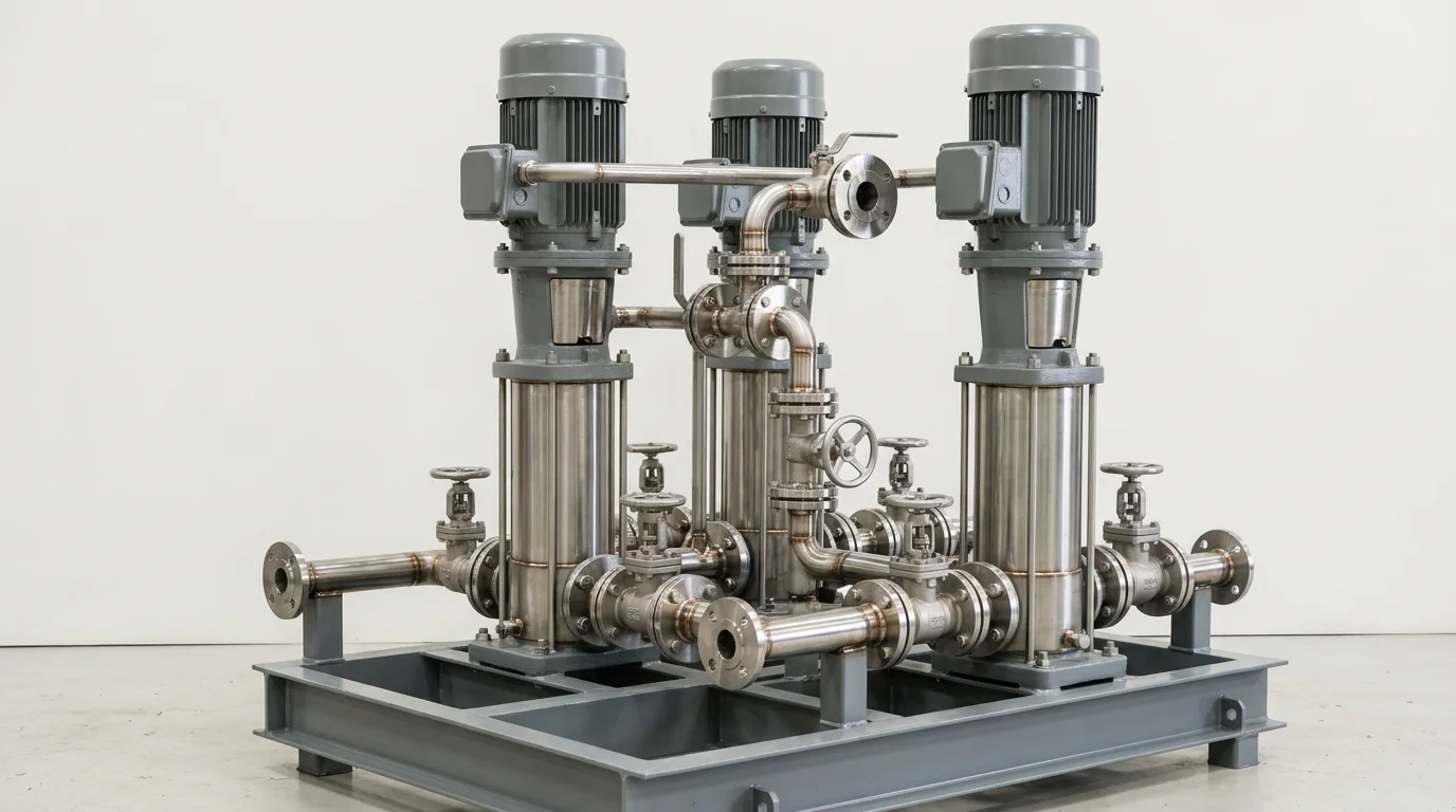
Series vs Parallel Pumps: Sizing Industrial RO Booster Pump Sets, Multistage Configurations & Flow Balancing Engineering Standard
A definitive rotating machinery hydraulic configuration manual, composite H-Q curve addition standard, and high-pressure reverse osmosis (RO) booster sizing guide for plant managers, water treatment consultants, and utility superintendents across Ahmedabad, Surat, Ankleshwar, Dahej, and Gujarat.
Quick Answer
In industrial reverse osmosis (RO) desalination plants, Common Effluent Treatment Plant (CETP) Zero Liquid Discharge (ZLD) installations, and high-pressure boiler feed facilities across Gujarat—spanning Ahmedabad (Vatva, Naroda, Sanand), Surat (Pandesara, Sachin), Ankleshwar GIDC, and Dahej PCPIR—system designers constantly face a critical hydraulic decision: should pumps be configured in series or in parallel? Misconfiguring pump trains creates severe operational failures: putting identical pumps in parallel on steep friction systems yields only a marginal 10% - 20% flow increase while pushing pumps into destructive dead-head recirculation, whereas staging pumps in series without verifying secondary casing design pressure causes catastrophic casing rupture and mechanical seal blowout. Operating industrial pump sets safely requires mastering the composite Head-Capacity (H-Q) curve physics: series configurations add dynamic head at constant flow (H_total = H_1(Q) + H_2(Q)) to overcome high membrane osmotic back-pressures (15 - 70 bar), while parallel configurations add flow capacity at constant head (Q_total = Q_1(H) + Q_2(H)) for variable plant production demands conforming to ISO 5199, ISO 2858, IS 5120, and IS 1520 standards.
Key Takeaways
- Series Configuration Adds Head at Constant Flow. Staging pumps in series adds discharge heads (H_1 + H_2) to overcome high RO membrane osmotic pressures (15 - 70 bar).
- Parallel Configuration Adds Flow at Constant Head. Operating pumps in parallel adds capacities (Q_1 + Q_2) to satisfy fluctuating plant water demand.
- Verify Secondary Pump Casing Pressure Ratings in Series Trains. The second stage pump casing is subjected to the full discharge pressure of the first stage.
- Protect Parallel Pumps Against Unequal Flow Dead-Heading. Install fast-acting non-return check valves and individual flow meters on each pump branch.
Introduction
Across Gujarat's major industrial water treatment centers—concentrated in Ahmedabad (Vatva, Naroda, Sanand), Surat (Pandesara, Sachin), Ankleshwar GIDC, and Dahej PCPIR—reverse osmosis (RO) filtration systems, CETP effluent recycling plants, and high-pressure boiler feed networks operate continuously.
Water treatment plant managers, environmental engineers, and utility consultants face critical design choices when engineering pump sets:
- The High-Head Demand: High-recovery RO membranes treating high-TDS effluent (15,000 - 45,000 ppm) require driving pressures of 35 - 70 bar (350 - 700 meters head) to overcome osmotic resistance. Achieving this head with a single standard end-suction pump is impossible, necessitating series staging or specialized high-pressure multistage assemblies.
- The Flow Balancing Challenge: In parallel booster trains, minor differences in pump wear or motor speeds cause one pump to hog flow while pushing the weaker pump into dead-head recirculation, leading to rapid bearing overheating and seal failure.
- The Engineering Standard: Designing series and parallel systems conforming to ISO 5199, ISO 2858, IS 5120, and IS 1520 standards—verifying secondary casing pressure ratings, plotting accurate composite H-Q curves, installing fast-acting dual-plate check valves, and integrating VFD load sharing—guarantees stable hydraulic operation, low energy consumption, and maximum membrane throughput.
2. Master Series vs Parallel Hydraulic Comparison & Sizing Matrix
Review the fundamental architectural differences, hydraulic scaling laws, and engineering selection rules for series and parallel pump configurations:
| Parameter / Feature | Series Pump Configuration (H_total = H_1 + H_2) | Parallel Pump Configuration (Q_total = Q_1 + Q_2) |
|---|---|---|
| Primary Hydraulic Function | Multiplies Total System Head at Constant Flow | Multiplies Delivered Flow Capacity at Constant Head |
| Composite Curve Math | H_composite(Q) = H_1(Q) + H_2(Q) (Add Vertically) | Q_composite(H) = Q_1(H) + Q_2(H) (Add Horizontally) |
| Typical Target Applications | High-Pressure RO Boosters, Boiler Feed, Long Pipelines | Raw Water Intake, Cooling Towers, Variable Plant Demand |
| Casing Pressure Rating Need | Stage 2 Casing must withstand P_1 + ΔP_2 (High Class) | All pump casings rated for single-pump discharge pressure |
| NPSH_a Sensitivity | Critical only on 1st Stage; 2nd Stage has high suction head | Every parallel pump requires adequate NPSH_a from header |
| Flow Control Strategy | Single VFD on motor or bypass control | Individual VFDs per pump with auto-balancing controllers |
| Check Valve Criticality | Prevents reverse flow if 1st stage trips | Mandatory to prevent back-spinning when 1 pump is offline |
Interactive 5-Year Total Cost of Ownership (TCO) Simulator
Sealless Mag-Drive vs Mechanically Sealed Chemical Pump3. The Hydraulic Physics, Composite H-Q Curves & Osmotic Math
Series Hydraulic Scaling & Composite Curve Addition (H_total = H_1 + H_2)
When pumps operate in series, the discharge of the primary (lead) pump is piped directly into the suction nozzle of the secondary (booster) pump:
To construct the composite curve, select multiple flow points (Q) across the operating range and sum the heads vertically. If Pump 1 generates 30 bar (300 m) at 50 m³/h and Pump 2 generates 35 bar (350 m) at the same flow, the series pair delivers 65 bar (650 m) at 50 m³/h.
Parallel Hydraulic Scaling & Composite Curve Addition (Q_total = Q_1 + Q_2)
When pumps operate in parallel, both pumps draw from a common suction header and discharge into a common discharge manifold:
To construct the composite curve, select multiple head points (H) and sum the flow capacities horizontally. If each pump delivers 100 m³/h at 40 m head, the parallel pair theoretically delivers 200 m³/h at 40 m head.
System Friction Curve Intersections & Diminishing Flow Returns in Parallel Trains
A common engineering mistake is assuming that operating two identical pumps in parallel doubles delivered system flow:
- The Friction Curve Reality: System total head consists of static head (H_static) and friction head (h_f = k · Q²). Because friction increases with the square of the flow rate, the system head curve rises steeply.
- Diminishing Returns: In systems with long piping and high friction loss, adding a second parallel pump increases total flow by only 15% - 30%, not 100%. As flow increases, individual pump operating points shift to the left along their curves, reducing individual pump efficiency.
Reverse Osmosis Membrane Osmotic Pressure & High-Pressure Booster Staging Math
In high-recovery reverse osmosis systems, feed water must overcome the natural osmotic pressure of the concentrated salt solution:
For CETP wastewater with 30,000 ppm TDS, osmotic back-pressure is 24 bar. Adding membrane friction losses (3 bar) and required net driving pressure (15 bar) requires a total feed pressure of 42 bar (420 m head).
Staging a primary low-NPSH feed booster (6 bar) with a high-pressure Super Duplex multistage pump (36 bar) in series provides the required 42 bar while completely protecting against suction cavitation.
4. The 4 Critical Failure Modes in Series vs Parallel Pump Installations
Failure Mode 1: Secondary Stage Casing Over-Pressurization in Series Trains
- Root Cause: Feeding the discharge of a 25 bar pump into a standard Class 150 (16 bar rated) secondary pump casing, causing catastrophic casing rupture or flange gasket blowout.
- Engineering Solution: Specify Class 300 or Class 600 heavy-duty ductile iron or forged duplex stainless steel casings for all secondary stage pumps in series trains.
Failure Mode 2: Dead-Head Recirculation in Asymmetric Parallel Pumps
- Root Cause: Operating mismatched pumps in parallel; the higher-head pump forces the check valve of the weaker pump shut, causing the weaker pump to overheat and vaporize liquid within minutes.
- Engineering Solution: Install identical pump hydraulics, balance speeds with VFDs, and install minimum flow automatic recirculation valves (ARVs).
Failure Mode 3: Reverse Impeller Spinning & Seal Blowout from Check Valve Failure
- Root Cause: A jammed or leaking non-return valve allows high-pressure discharge manifold fluid to flow backward through an idle parallel pump, spinning it in reverse at high RPM and shattering mechanical seal faces.
- Engineering Solution: Install high-performance, spring-assisted dual-plate wafer check valves with soft-closing dampeners.
Failure Mode 4: Cavitation Inception in Primary Low-NPSH Suction Boosters
- Root Cause: Attempting to generate high pressure with a single large pump with high NPSH_r from an atmospheric feed tank, causing intense suction cavitation.
- Engineering Solution: Install a low-speed, low-NPSH primary booster pump in series to provide positive suction head to the main high-pressure pump.
5. Sanitary Materials of Construction & Cleanroom Standards
Super Duplex Stainless Steel (UNS S32750 / 2507) & Duplex SS (UNS S31803)
- High-TDS RO Boosters: Investment-cast Super Duplex SS (PREN > 42) or Duplex SS (UNS S31803) impellers and intermediate stage casings offering total immunity to chloride pitting (> 30,000 ppm TDS) and high mechanical tensile strength.
SS316L Investment Castings for Demineralized & Permeate Water
- Low-Conductivity Water: Investment-cast SS316L pump wet ends with electro-polished internal passages for demineralized (DM) water and permeate transfer lines.
Solid Isostatic PTFE & PVDF Chemical Dosing Pumps
- Antiscalant & Acid Dosing: Solid isostatic PTFE or virgin PVDF chemical dosing pumps for metering sulfuric acid and antiscalant chemicals into RO feed streams.
Monolithic Direct-Sintered Silicon Carbide (SSiC) High-Pressure Seals
- High-Pressure Mechanical Seals: Heavy-duty cartridge mechanical seals with monolithic direct-sintered SSiC vs SSiC faces and balanced stationary seats rated for operating pressures up to 75 bar.
6. Step-by-Step Series vs Parallel Sizing & Installation SOPs
Execute these structured engineering SOPs when designing series and parallel pump configurations:
Phase 1: RO Membrane Osmotic Pressure & System Curve Audit SOP
- TDS & Osmotic Math: Determine feed TDS, operating temperature, and membrane recovery rate. Calculate required net driving pressure and total system head.
- System Curve Generation: Plot static head and friction loss curve (H_system = H_static + k · Q²).
Phase 2: Series vs Parallel Hydraulic Configuration Selection SOP
- Head vs Flow Assessment:
- If required head exceeds single-stage capability (> 25 bar) at constant flow -> Select Series Configuration. - If flow demand fluctuates widely (50% - 200%) at constant system head -> Select Parallel Configuration.
Phase 3: Series Casing & Seal Chamber Maximum Pressure Audit SOP
- Cumulative Pressure Math: Compute maximum dead-head pressure on the second stage pump:
- Casing Rating Check: Verify second stage casing, flanges, and mechanical seal gland are rated for P_max,stage 2 with a 1.5× safety factor.
Phase 4: Parallel Pump VFD Speed Matching & Flow Balancing SOP
- Speed Synchronization: Equip each parallel pump with an independent Variable Frequency Drive (VFD).
- Flow Control Loop: Install individual magnetic flow meters on each pump discharge branch to balance flow delivery and prevent pump fighting.
Phase 5: Non-Return Valve & Water Hammer Surge Protection SOP
- Check Valve Installation: Install spring-loaded dual-plate check valves on each pump discharge branch before the isolation valve.
- Surge Vessel Sizing: Install a nitrogen-charged bladder surge vessel on high-pressure headers to suppress hydraulic water hammer shocks during sudden trips.
Phase 6: On-Site Commissioning & Hydraulic Performance Proof SOP
- Staged Startup: For series trains, start primary booster pump first; confirm positive suction pressure (> 3 bar) before starting high-pressure secondary pump.
- Pressure & Vibration Proof: Record suction and discharge pressures across each stage; verify overall vibration velocity is < 2.8 mm/s RMS (ISO 5199 Zone A).
7. Worked Gujarat Water Treatment, CETP & Desalination Case Studies
Case 1: Ahmedabad Vatva CETP ZLD High-Pressure RO Booster Sizing
- Plant Context: A Zero Liquid Discharge (ZLD) effluent recycling plant in Vatva GIDC treating high-COD/high-TDS textile dye wastewater (40,000 ppm TDS, 60 m³/h at 55 bar required head).
- Problem: Sourced a single large multistage pump that suffered chronic suction cavitation due to low suction head and high NPSH_r (4.5 m).
- Action Plan: Teflow engineering team designed a series configuration:
- Stage 1: Low-speed end-suction feed booster (NPSH_r = 1.2 m) delivering 6 bar. - Stage 2: Super Duplex SS32750 high-pressure multistage pump delivering additional 49 bar with a Class 600 casing.
- Outcome: Suction cavitation eliminated 100%; stable 55 bar membrane feed pressure achieved; continuous trouble-free operation across 24 consecutive operating months; saved Rs 14,50,000 in avoided membrane fouling and seal replacements.
Case 2: Surat Pandesara Textile Effluent RO Membrane Series Staging
- Plant Context: A textile processing CETP in Pandesara GIDC (Surat) operating two 150 m³/h RO trains.
- Problem: High feed TDS (28,000 ppm) caused membrane scaling when pressure dropped below 38 bar.
- Action Plan: Installed two Duplex SS pumps in series with VFD speed control to maintain constant 42 bar feed pressure.
- Outcome: Membrane permeate recovery increased from 68% to 82%; zero downtime over 22 consecutive operating months.
Case 3: Dahej PCPIR Seawater Desalination RO High-Pressure Booster
- Plant Context: A seawater desalination facility in Dahej PCPIR generating potable water (65 bar, 200 m³/h).
- Problem: Severe check valve slam caused high pressure spikes (> 90 bar) during power trips.
- Action Plan: Replaced conventional swing checks with fast-closing dual-plate non-slam check valves and integrated an isobaric energy recovery device (ERD).
- Outcome: Surge pressure peaks suppressed below 70 bar; specific energy consumption dropped from 3.8 kWh/m³ to 2.2 kWh/m³.
Case 4: Sanand Automotive Plant Demineralized Water Parallel Booster Train
- Plant Context: An automobile manufacturing facility in Sanand GIDC supplying DM water to paint shops (50 - 300 m³/h fluctuating demand at 4.5 bar).
- Problem: Single large pump operated far to the left of BEP during night shifts, wasting power and overheating.
- Action Plan: Installed three identical 100 m³/h SS316L pumps in parallel with automated PLC staging based on header pressure.
- Outcome: Power consumption reduced by 38% during low-demand shifts; saved Rs 8,20,000 annually in electricity.
Case 5: Ankleshwar GIDC High-TDS Solvent Recovery Stripper Feed Boosters
- Plant Context: A chemical active plant in Ankleshwar GIDC feeding stripping columns at 18 bar pressure.
- Problem: Corrosive solvent attacks caused regular pump casing leaks.
- Action Plan: Supplied two solid PTFE lined pumps operating in series with heavy-duty ductile iron armor shells.
- Outcome: Zero corrosion leaks; mechanical seals ran without leakage over 24 consecutive operating months.
Case 6: Gandhinagar Central Thermal Power Station Boiler Feed Series Staging
- Plant Context: A utility boiler feed system in Gandhinagar operating high-pressure feed water trains (85 bar at 140°C).
- Problem: Deaerator low elevation caused suction cavitation in main boiler feed pumps.
- Action Plan: Placed a low-speed booster pump upstream in series to supply 8 bar positive suction pressure.
- Outcome: Cavitation noise eliminated; boiler feed availability restored to 100%.
8. Step-by-Step Series vs Parallel Selection Decision Matrix
Follow this structured engineering guide when selecting between series and parallel pump configurations in Gujarat:
| System Process Requirement | Recommended Hydraulic Architecture | Critical Engineering Rule |
|---|---|---|
| Total Head > 25 bar (250 m) at Constant Flow | Series Staging (Booster + High-Pressure Pump) | Ensure Stage 2 casing is rated for full cumulative shutoff head |
| Low Available NPSH_a with High Head Demand | Series Configuration (Low-NPSH Lead Pump) | Use low-speed lead pump to boost suction head to main pump |
| Wide Fluctuating Flow Demand (50% - 200%) | Parallel Configuration (Multiple Identical Pumps) | Equip each pump with VFD and individual check valve |
| High Friction Head System (h_f > 60% of Head) | Series Configuration (Avoid Parallel Staging) | Parallel pumps yield minimal flow increase on steep curves |
| High Chloride / Seawater RO (> 20,000 ppm TDS) | Super Duplex SS (UNS S32750) Series Boosters | Specify PREN > 42 metallurgy to prevent crevice corrosion |
| Demineralized / High-Purity Permeate Water | SS316L Parallel Booster Train | Use electro-polished wet ends with sanitary tri-clamp seals |
9. Comprehensive Master RO Booster & Hydraulic Quality (FAT) Checklist
Execute this quality verification protocol before commissioning series or parallel high-pressure pump sets:
Series vs Parallel Pump Architecture & Quality (FAT) Protocol
10. Summary & High-Pressure Hydraulic Engineering Support in Gujarat
Eliminating destructive dead-head recirculation in parallel booster trains, preventing secondary casing rupture in high-pressure series installations, overcoming extreme membrane osmotic resistance in CETP Zero Liquid Discharge (ZLD) systems, and guaranteeing rotating machinery reliability across Ahmedabad (Vatva, Naroda, Sanand), Surat (Pandesara, Sachin), Ankleshwar GIDC, and Dahej PCPIR—by utilizing first-principles composite H-Q curve calculations, Super Duplex SS32750 and Duplex SS31803 metallurgy, monolithic SSiC mechanical seals, and dynamic rotor balancing conforming to ISO 5199, ISO 2858, IS 5120, and IS 1520 standards—is the proven engineering standard for industrial water treatment and high-pressure pumping.
Partnering directly with an established Gujarat rotating machinery manufacturer provides plant managers, water treatment consultants, and utility superintendents with immediate technical access to hydraulic system modeling, composite curve evaluations, high-pressure multistage assemblies, and genuine spares. Our technical engineers provide on-site pump system audits, RO booster proposals, and complete engineering consultations.
Teflow Pumps operates a specialized high-pressure and chemical machinery manufacturing facility in Ahmedabad, providing engineered Super Duplex RO booster pumps, multistage boiler feed pumps, PFA-lined process pumps, solid PTFE pumps, precision mechanical seals, dynamic rotor balancing, and genuine rotating equipment spares across Gujarat conforming to ISO 5199, ISO 2858, IS 5120, and API 685 standards.
- Direct Technical & Emergency Helpline: +91 98251 62709
- WhatsApp Technical Desk: Share RO feed TDS (ppm), membrane operating pressure (bar), required flow rate (m³/h), or current pump nameplate photos to wa.me/919825162709 for immediate technical review, composite H-Q sizing verification, and formal quotation.
- Request an On-Site RO Booster & High-Pressure Pump Audit Survey: Contact our senior rotating equipment engineers for plant pump surveys, hydraulic sizing proposals, and formal quotation. Our engineering team conducts comprehensive hydraulic system audits, calculates exact series and parallel operating intersections, verifies secondary casing pressure containment, and certifies custom pump assemblies to ensure maximum uptime across Gujarat's industrial processing clusters. We provide rapid technical evaluations, on-site plant surveys, and formal quotes.
Related Reading
- Total head calculation for pumps: static lift and pipe friction loss guide
- Industrial pump repair and overhaul services
- Teflon lined and chemical pumps overview
- Series vs parallel pumps for RO booster sizing guide
- Chemical pipe sizing and velocity limits guide
- ETP, CETP and wastewater sump pump overhaul services