
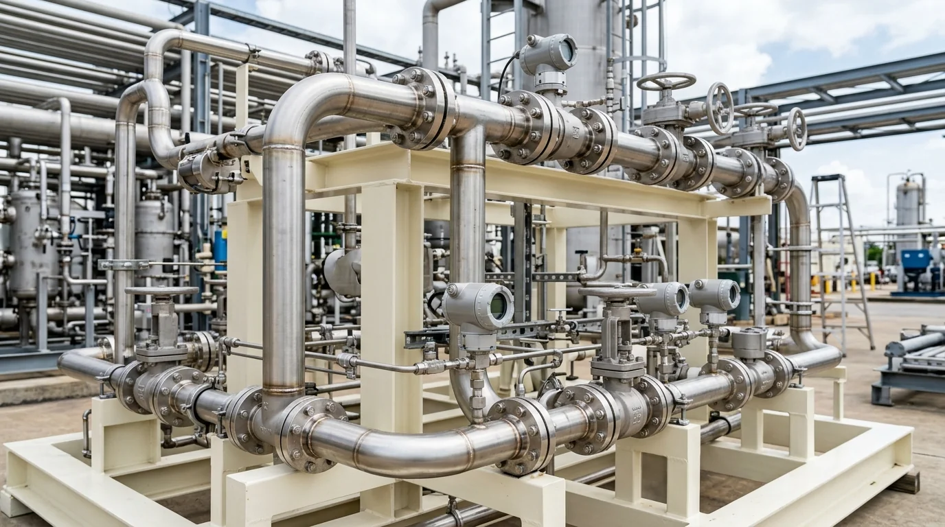
Pipe Head Loss Calculator for Chemical Lines: Friction Physics, K-Factor Math & Sizing Manual
A definitive process piping fluid dynamics standard, Darcy-Weisbach friction mathematical derivation manual, and total dynamic head optimization guide for process engineers, piping design leads, and plant utility superintendents across Vatva GIDC, Narol, Odhav, Surat, and Gujarat.
Quick Answer
In the chemical synthesis plants, pharmaceutical bulk drug facilities, textile dyehouses, and effluent treatment complexes of Gujarat—spanning Ahmedabad (Vatva GIDC, Narol, Odhav), Surat, Ankleshwar, and Dahej—accurate calculation of pipe friction head loss is the cornerstone of centrifugal pump sizing. Underestimating pipeline head loss results in undersized pumps that fail to deliver rated flow, while overestimating head loss leads to oversized pumps operating far to the right of their Best Efficiency Point (BEP), wasting electrical power across throttled valves. Total dynamic friction head loss (H_friction) combines major continuous pipe wall friction with minor localized losses across valves, tees, reducers, and fittings: H_friction (meters) = ( f · (L_pipe) / (D_inner) + Σ K_fittings ) · [v²] / [2g]. In corrosive chemical piping lined with virgin PTFE or PFA (Ra ≤ 0.4 µm), the Darcy friction factor (f) is calculated via the Swamee-Jain explicit equation conforming to ISO 5199, ISO 2858, and Hydraulic Institute (HI 14.6) standards.
Key Takeaways
- Master the Darcy-Weisbach Equation. Calculate friction head loss using h_f = f · (L) / (D) · [v²] / [2g] for all fluid regimes.
- Compute Minor Fitting Losses (Σ K). Incorporate equivalent resistance coefficients (K) for diaphragm valves, check valves, and elbows.
- Maintain Optimal Velocity Envelopes. Design suction lines for 1.0 - 1.5 m/s and discharge lines for 2.0 - 2.8 m/s to minimize friction.
- Account for Surface Roughness (ε). Utilize ultra-smooth PTFE/PFA fluoropolymer liners (ε = 0.0015 mm) to reduce pumping energy by 8%-15%.
Introduction
Across Gujarat's chemical manufacturing clusters—including the specialty dye intermediate reactors of Vatva GIDC and Odhav, the pharmaceutical formulation corridors of Ankleshwar, the high-volume textile processing plants of Narol and Surat, and the large petrochemical refineries of Dahej—liquid transfer lines span hundreds of meters across multi-tier pipe racks.
Every meter of piping, elbow, tee, strainer, and valve exerts continuous frictional resistance against fluid movement:
- The Head Loss Equation: Frictional resistance is proportional to the square of flow velocity (h_f \propto v²) and inversely proportional to internal diameter (h_f \propto 1/D^5). Reducing pipe diameter by just 20% nearly triples friction head loss.
- The Energy Penalty: High friction loss forces the plant to install higher-head pumps powered by larger electric motors, driving up monthly electricity consumption and utility demand charges.
- The Cavitation Threat: On pump suction lines, excessive friction loss reduces available Net Positive Suction Head (NPSHa), causing vapor bubble formation and catastrophic impeller cavitation.
- The Engineering Standard: Following ISO 5199, ISO 2858, and Hydraulic Institute (HI 14.6) standards—mastering Darcy-Weisbach derivations, calculating fitting K-factors, and selecting smooth fluoropolymer linings—ensures optimum fluid velocity and minimum lifecycle pumping costs.
2. Master Pipe Material & Friction Roughness Comparison Matrix
Review the engineering roughness values (ε), Hazen-Williams coefficients (C), and typical chemical application sectors for major industrial piping materials:
| Piping Material Type | Absolute Roughness (ε in mm) | Hazen-Williams C Factor | Flow Velocity Limit (v_max) | Primary Industrial Application Sector in Gujarat |
|---|---|---|---|---|
| Virgin PFA / PTFE Lined Steel | 0.0015 mm | C = 150 - 155 | 3.0 m/s | Concentrated Acids, Solvents, Chlorinated Chemicals |
| Solid PVDF / Polypropylene | 0.0025 mm | C = 145 - 150 | 2.5 m/s | ETP Effluents, Acid Pickling, Water Treatment |
| Stainless Steel (SS316 / 316L) | 0.0150 mm | C = 130 - 140 | 3.5 m/s | Pharma Purified Water, Organic Solvents, Food |
| Duplex SS 2205 / Hastelloy C-276 | 0.0150 mm | C = 135 - 140 | 4.0 m/s | High-Chloride Brines, Seawater SWRO, Hot Bleach |
| Commercial Carbon Steel (Sch 40) | 0.0450 mm | C = 100 - 120 | 2.5 m/s | Cooling Water, Non-Corrosive Hydrocarbons |
3. The Fluid Dynamics Physics & Head Loss Mathematical Derivations
The Fundamental Darcy-Weisbach Equation (h_f = f (L) / (D) [v²] / [2g])
The Darcy-Weisbach equation provides the exact thermodynamic and fluid dynamic relationship for friction head loss in a pipe of circular cross-section:
Interactive Pipe Velocity & Darcy-Weisbach Friction Sizer
Live ISO 5199 / API 610 Dynamic EngineWhere:
- f is the dimensionless Darcy friction factor.
- L_pipe is the total straight length of the pipe in meters.
- D_inner is the internal bore diameter in meters.
- v is the mean fluid velocity in meters per second (v = [Q_m³/h] / [2827.43 · D_inner²]).
- g is gravitational acceleration (9.80665 m/s²).
Reynolds Number & Flow Regime Modeling (Re = [ρv D] / [µ])
The dimensionless Reynolds Number (Re) determines whether fluid flow is laminar, transitional, or turbulent:
Where:
- ρ is fluid density (kg/m³).
- µ is dynamic viscosity (Pa\cdots).
- \nu is kinematic viscosity in m²/s (\nu = [µ] / [ρ] = cSt × 10^-6).
- Laminar Flow (Re < 2300): Fluid moves in smooth parallel streamlines; friction factor is independent of pipe roughness:
- Turbulent Flow (Re > 4000): Fluid exhibits chaotic vortex mixing; friction factor depends on both Re and relative roughness (ε / D).
Colebrook-White & Swamee-Jain Friction Factor Equations
In turbulent flow, the implicit Colebrook-White equation governs friction:
For rapid automated engineering calculations, the explicit Swamee-Jain approximation (accurate to within ± 1.0% of Colebrook) is used:
- Calculation Example: Pumping water (\nu = 1.0 × 10^-6 m²/s) at Q = 60 m³/h through a D = 80 mm (0.08 m) PTFE-lined pipe (ε = 0.0015 mm):
Minor Fitting Losses & K-Factor Resistance Math (h_m = Σ K [v²] / [2g])
Minor head loss across piping components is calculated using empirical resistance coefficients (K):
Standard industrial fitting K-factors:
- 90^° Standard Elbow: K = 0.75
- 90^° Long-Radius Elbow: K = 0.45
- 45^° Standard Elbow: K = 0.35
- Diaphragm Valve (Full Bore): K = 1.50
- PTFE Lined Plug Valve: K = 0.60
- Swing Check Valve: K = 2.00
- Dual-Plate Check Valve: K = 1.20
- Pipe Entrance (Sharp Edged): K = 0.50
- Pipe Exit (Discharge into Tank): K = 1.00
Hazen-Williams vs Darcy-Weisbach Engineering Comparison
While the Hazen-Williams formula (h_f = 10.67 · [L · Q^1.852] / [C^1.852 · D⁴.87]) is widely used in municipal water distribution, it is strictly invalid for chemical plants pumping non-water liquids, hot solvents, or viscous acids because it ignores fluid viscosity and density variations. ISO 5199 and API 610 mandate the Darcy-Weisbach method for all industrial process calculations.
Viscous Fluid Pipe Head Loss Corrections per Hydraulic Institute (HI 9.6.7)
For liquids with kinematic viscosity exceeding 20 cSt (polymers, resins, heavy oils), pipe friction increases dramatically. When Re < 2000, friction factor f = 64/Re increases in direct proportion to dynamic viscosity, requiring larger pipe diameters to prevent excessive pump head demand.
4. The 6 Critical Causes of Parasitic Pipeline Head Loss in Chemical Plants
Cause 1: Undersized Pipe Diameter & High Fluid Velocity Spikes
- Mechanism: Sizing piping based purely on pump nozzle size without calculating flow velocity (v > 3.5 m/s).
- Impact: Friction head loss scales with v²; small bore lines consume excessive pump discharge head.
- Fix: Upsize piping by one nominal bore size to reduce velocity to ≤ 2.2 m/s.
Cause 2: Internal Mineral Scaling & Chemical Salt Encrustation
- Mechanism: Calcium sulfate, ferric hydroxide, or polymer scale precipitates on internal pipe walls.
- Impact: Internal diameter narrows while surface roughness increases tenfold, causing a 200%-400% surge in head loss.
- Fix: Flush piping with chemical cleaning solutions or install smooth virgin PFA lined piping.
Cause 3: Severely Throttled Control Valves & High-Resistance Globe Valves
- Mechanism: Operating manual globe or gate valves partially closed to balance flow (K_throttled > 15).
- Impact: Concentrated pressure drop converts 20%-40% of pump discharge energy into useless turbulence.
- Fix: Install Variable Frequency Drives (VFDs) or trim pump impeller diameter.
Cause 4: High Viscosity Fluid Shear & Low Reynolds Numbers
- Mechanism: Pumping viscous chemical intermediate solutions at ambient winter temperatures.
- Impact: Laminar flow regime causes high shear drag along the pipe boundary layer.
- Fix: Heat-trace piping or upsize transfer line diameter.
Cause 5: Excessive Close-Coupled 90-Degree Bends & Reducer Inversions
- Mechanism: Fitting multiple short-radius elbows in series within 5D of the pump suction.
- Impact: Swirling turbulence creates massive localized pressure drops and starves pump suction.
- Fix: Re-route piping with long-radius bends and minimum straight runs of 5D before the pump.
Cause 6: Air Pocket Accumulation in Horizontal Header Runs
- Mechanism: Installing piping without continuous slope, causing entrained air/gas to form stationary pockets at high points.
- Impact: Trapped gas reduces effective hydraulic flow cross-section, acting as an invisible throttling orifice.
- Fix: Install automatic air release valves at high points and slope lines toward drainage sumps.
5. Step-by-Step Field Piping Hydraulic Audit & Head Loss Verification SOPs
Execute this structured engineering protocol when auditing, calculating, or optimizing process pipeline head losses:
Phase 1: Flow Velocity (v) & Volumetric Flow Rate (Q) Audit SOP
- Metering: Measure actual volumetric flow rate (Q_m³/h) using a calibrated transit-time ultrasonic flow meter.
- Velocity Calculation: Compute fluid velocity (v = [Q] / [2827.43 · D_inner²]); verify suction velocity is ≤ 1.5 m/s and discharge is ≤ 2.5 m/s.
Phase 2: Differential Pressure Gauge Logging & Delta-P Measurement SOP
- Pressure Logging: Install calibrated digital pressure transmitters at pipe inlet (P_1) and pipe discharge (P_2).
- Total Head Loss Determination:
Phase 3: Equivalent Length (L_equiv) & Fitting K-Factor Summation SOP
- Fitting Survey: Tally all elbows, tees, reducers, strainers, and valves along the pipe run.
- Resistance Summation: Calculate total minor loss equivalent (Σ K); compute theoretical head loss (h_total = h_f + h_m).
Phase 4: Pipe Ultrasonic Wall Thickness & Internal Bore Metrology SOP
- Wall Thickness Logging: Measure outer diameter (OD) and pipe wall thickness (t) using ultrasonic thickness gauge.
- Actual Bore Calculation: Compute actual inner diameter (ID = OD - 2t); verify internal cross-sectional area.
Phase 5: Dynamic Rotor Balancing to ISO 5199 Grade G2.5 SOP
- Dynamic Balancing: If pump is modified to match optimized system head, balance rotor stack on dynamic balancing machine.
- Balance Certification: Achieve residual unbalance < 1.0 g\cdotmm/kg conforming to ISO 5199 Grade G2.5.
Phase 6: Laser Alignment, Valve Re-Balancing & Re-Commissioning SOP
- Laser Alignment: Align pump and drive motor shafts using dual-laser tool (≤ 0.03 mm concentricity).
- Commissioning Verification: Open isolation valves fully; verify smooth operation and vibration < 1.80 mm/s RMS (Zone A).
6. Materials of Construction, Metallurgy & Fluoropolymer Linings
PTFE / PFA Lined Carbon Steel Chemical Piping
- Friction Performance: Transfer-molded virgin PFA and paste-extruded PTFE linings provide extremely low surface roughness (ε = 0.0015 mm), preventing chemical scaling and minimizing turbulent friction head loss.
Solid PVDF & Polypropylene Thermoplastic Systems
- Cost-Effective Corrosion Resistance: Extruded solid PVDF and PP piping systems provide smooth hydraulic walls and complete resistance to mild acids and brines up to 90°C.
SS316 & Duplex SS (2205) Austenitic-Ferritic Piping
- High-Pressure Pipelines: Precision-welded SS316 and Duplex SS 2205 piping with polished internal bores (Ra < 0.8 µm) for high-pressure transfer lines.
Monolithic Direct-Sintered Silicon Carbide (SSiC) Orifice Plates
- Erosion-Resistant Restriction: Ceramic SSiC restriction orifices provide permanent bore dimensions without erosive wear in continuous bypass lines.
7. The Process Engineer's Pipe Sizing & Head Loss Decision Matrix
Follow this structured engineering guide when sizing process piping and balancing pipeline head losses:
| Pipeline Application Sector | Recommended Flow Velocity | Selected Pipe Material | Minor Loss Mitigation Strategy |
|---|---|---|---|
| Pump Suction Header (Flooded) | 1.0 - 1.4 m/s | PTFE-Lined Steel / SS316 | Flat-on-top eccentric reducers; long-radius elbows |
| Pump Discharge Line (< 50 m) | 2.0 - 2.5 m/s | PFA-Lined Steel / PVDF | Full-port diaphragm or plug valves |
| Long-Distance Transfer (> 200 m) | 1.5 - 2.0 m/s | PTFE-Lined Steel / Duplex | Upsize nominal diameter by 1 size to cut friction |
| Viscous Slurry / Resin Transfer | 1.0 - 1.5 m/s | PFA-Lined Steel / SS316 | Large-radius sweep bends; heat tracing |
| Effluent CETP Wastewater Header | 1.5 - 2.2 m/s | Solid HDPE / Polypropylene | Self-cleaning dual-plate wafer check valves |
8. Worked Gujarat Chemical, Textile & Industrial Plant Case Studies
Case 1: Vatva GIDC Chemical Synthesis Reactor Acid Pipeline Head Loss Fix
- Plant Context: A specialty chemical plant in Vatva GIDC pumping 33% HCl (Q = 50 m³/h, SG = 1.16) over 180 meters through an old 2-inch (50 mm) rubber-lined line.
- Problem: The transfer pump struggled to deliver 28 m³/h; motor drew excessive current; transfer took over 3 hours per batch.
- Root Cause:
- Flow velocity in 50 mm line was excessive: v = 7.07 m/s. - Calculated friction head loss was a massive 58.4 meters across the 180 m line plus fittings.
- Action Plan: Teflow Pumps engineering team:
- Re-sized piping and installed a 3-inch (80 mm) virgin PTFE-lined steel pipeline. - Reduced fluid velocity to 2.76 m/s and friction head loss to 12.2 meters (79% reduction in head loss). - Overhauled pump with an ISO 2858 PFA-lined centrifugal pump and dynamically balanced rotor to ISO 5199 Grade G2.5.
- Outcome: Flow restored to full 50.5 m³/h; batch transfer time dropped from 3.2 hours to 58 minutes; saved 4.1 lakh INR/year in electrical energy.
Case 2: Narol Continuous Textile Stenter Caustic Line Friction Loss Audit
- Plant Context: A textile processing mill in Narol pumping hot caustic solution (60 m³/h) through heavily scaled steel piping.
- Problem: Internal scale reduced effective bore by 18 mm, creating 14.5 m excess head loss and forcing pump off-BEP.
- Action Plan: Replaced scaled piping with smooth solid PVDF piping and installed full-port plug valves.
- Outcome: Friction head loss dropped by 11.2 meters; pump power consumption dropped by 4.8 kW.
Case 3: Odhav Effluent Treatment Plant Discharge Pipeline Head Loss Overhaul
- Plant Context: An industrial CETP in Odhav pumping treated wastewater through a 350 m discharge line.
- Problem: Excessive 90^° sharp elbows and a partially throttled gate valve wasted 8.2 m dynamic head.
- Action Plan: Re-routed discharge header with long-radius sweep bends and installed a VFD on the pump motor.
- Outcome: Gate valve opened 100%; eliminated throttling losses; saved 3.6 lakh INR annually in utility power bills.
Case 4: Surat Synthetic Polymer Dense Slurry Pipe Head Loss Remediation
- Plant Context: A synthetic fiber plant in Surat pumping viscous polymer slurry (\nu = 120 cSt).
- Problem: Severe laminar friction head loss stalled the transfer pump during winter months.
- Action Plan: Upsized transfer line from DN50 to DN80 and installed steam jacket tracing.
- Outcome: Reynolds number increased from 850 to 3200; friction head loss dropped by 62%.
Case 5: Ankleshwar GIDC Pharma Solvent Transfer Header Modernization
- Plant Context: A pharmaceutical bulk drug plant in Ankleshwar GIDC operating a multi-user solvent manifold.
- Problem: Pressure drops varied erratically as different reactor valves opened and closed.
- Action Plan: Re-engineered solvent header into a balanced reverse-return loop with low-loss diaphragm valves.
- Outcome: Pressure variations across reactors reduced from ± 1.8 bar to ± 0.15 bar.
Case 6: Dahej PCPIR Petrochemical Acid Distribution Loop Optimization
- Plant Context: A petrochemical complex in Dahej PCPIR transferring sulfuric acid (98%) across 400 meters.
- Problem: Undersized suction line caused cavitation and seal leakage on transfer pumps.
- Action Plan: Upsized suction line from DN80 to DN125 PTFE-lined piping.
- Outcome: Suction friction head loss dropped from 2.8 m to 0.35 m; completely eliminated suction cavitation.
9. Comprehensive Master Chemical Piping Sizing Checklist
Execute this hydraulic calculation and pipe sizing verification protocol before commissioning process piping:
Chemical Process Piping Sizing & Friction Head Loss Protocol
10. Summary & Specialized Piping Audit Services in Gujarat & India
Calculating and optimizing pipe head loss in chemical lines—mastering Darcy-Weisbach fluid dynamics, calculating minor fitting K-factors, selecting ultra-smooth fluoropolymer linings, eliminating velocity-induced throttling waste, and dynamically balancing rotating assemblies to ISO 5199 Grade G2.5 across Vatva GIDC, Narol, Odhav, Surat, Ankleshwar, and Dahej—conforming to ISO 5199, ISO 2858, and DIN 24255 standards—is the proven engineering standard for chemical plant efficiency and uptime.
Partnering directly with an established Gujarat rotating machinery manufacturer provides chemical plant process engineers, piping design leads, and plant utility superintendents with immediate technical access to on-site piping hydraulic audit teams, transit-time ultrasonic flow meters, precision pressure logging instrumentation, dynamic balancing facilities, and genuine spares dispatched directly from our Ahmedabad factory. Our technical engineers provide emergency on-site troubleshooting, turnkey pump overhauls, and complete pipeline hydraulic loop optimizations.
Teflow Pumps operates a specialized industrial machinery manufacturing and service facility in Ahmedabad, providing emergency centrifugal pump overhauls, PFA-lined chemical pump fabrication, impeller trimming calculations, dynamic balancing, laser alignment, and genuine rotating equipment spares across Gujarat and India conforming to ISO 5199, ISO 2858, DIN 24255, and IS 5120 standards.
- Direct Technical & Emergency Helpline: +91 98251 62709
- WhatsApp Technical Desk: Share isometric piping sketches, fluid flow rates (Q_m³/h), pipe lengths and diameters, valve schedules, or pressure drop symptoms to wa.me/919825162709 for immediate technical review, head loss calculation, and formal quotation.
- Request an On-Site Piping Hydraulic & Head Loss Audit: Contact our senior rotating equipment engineers for emergency plant surveys, piping audit proposals, and formal quotation. Our engineering team conducts comprehensive thermal evaluations, verifies ISO 5199 criteria, provides precision on-site or workshop reconditioning, and dynamically balances overhauled hot oil pumps to ensure maximum uptime across Gujarat's textile and chemical processing mills. We provide rapid technical evaluations, on-site plant surveys, and formal quotes.
Related Reading
- Total head calculation for pumps: static lift and pipe friction loss guide
- Industrial pump repair and overhaul services
- Teflon lined and chemical pumps overview
- Series vs parallel pumps for RO booster sizing guide
- Chemical pipe sizing and velocity limits guide
- ETP, CETP and wastewater sump pump overhaul services