
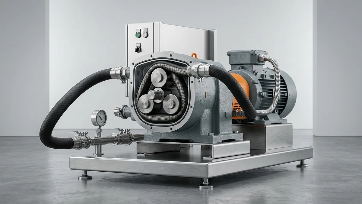
Peristaltic Pump Flow Rate Calculation for Dosing Skids: Sizing Math, Tube Physics & PTFE Diaphragm Comparison Manual
A definitive positive displacement dosing calculation guide, hose occlusion fluid mechanics standard, and chemical metering technology comparison for pharmaceutical formulation chemists, process engineers, and ETP superintendents across Vatva GIDC, Narol, Odhav, Surat, and Gujarat.
Quick Answer
In the active pharmaceutical ingredient (API) synthesis plants, biotechnology sterile fermentation suites, chemical intermediate units, and effluent treatment facilities of Gujarat—spanning Ahmedabad (Vatva GIDC, Narol, Odhav), Surat, Ankleshwar, and Dahej—accurate calculation of chemical dosing flow rates is fundamental to batch consistency. When engineering automated dosing skids, process engineers must choose between flexible-tube peristaltic pumps and solid Teflon (PTFE) diaphragm metering pumps. The volumetric flow rate delivered by a peristaltic roller pump is governed by the displaced volume of the squeezed elastomeric tube: Q_mL/min = 2 · π² · (r_tube)² · R_rotor · N_rpm · \eta_vol, converted to metric liters per hour via Q_L/h = [Q_mL/min × 60] / [1000]. While peristaltic pumps excel in low-pressure, shear-sensitive laboratory transfers and cell cultures, their delivered flow decays rapidly over time (often dropping by 15%-30% within 200 operating hours) due to elastomeric wall fatigue, tube wall dilation under backpressure, and loss of elastic springback. In continuous industrial chemical dosing applications (P_discharge > 3 bar), mechanically actuated virgin PTFE diaphragm pumps provide permanent volumetric stability conforming to ISO 5199, ISO 2858, and DIN 24255 standards.
Key Takeaways
- Master the Tube Occlusion Flow Formula. Use Q_mL/min = 2 · π² · r_inner² · R_rotor · N_rpm · \eta_vol to calculate theoretical peristaltic delivery rate.
- Account for Elastomeric Flow Decay. Peristaltic tube fatigue and mechanical creep cause flow rates to degrade by 10%-25% over 100 to 300 hours of continuous service.
- Evaluate Discharge Backpressure Limits. Peristaltic tubing loses volumetric efficiency rapidly above 2.0 bar; PTFE diaphragm pumps maintain precision up to 16 bar.
- Select the Right Technology for the Duty. Deploy peristaltic pumps for shear-sensitive biotech fluids; deploy PTFE diaphragm pumps for continuous aggressive chemical dosing.
Introduction
Across Gujarat's specialized chemical and pharmaceutical processing sectors—including the API bulk drug synthesis corridors of Ankleshwar and Vatva GIDC, the continuous textile dyehouses of Narol and Surat, and the large petrochemical complexes of Dahej—precision chemical metering is central to product quality and process yield.
When configuring chemical dosing skids, process engineers must balance metering accuracy, chemical compatibility, maintenance frequency, and total lifecycle costs:
- The Metering Technology Debate: Peristaltic pumps offer seal-less, valve-less fluid containment where liquid only contacts the disposable tube. However, continuous mechanical compression causes elastomeric fatigue, leading to unannounced flow decay and unexpected tube ruptures.
- The Hydraulic Pressure Limit: Peristaltic pumps suffer steep volumetric efficiency drops when pumping against discharge backpressures exceeding 2.0 to 3.0 bar. In contrast, mechanically and hydraulically actuated Teflon diaphragm pumps maintain linear ± 1.0% accuracy up to 16 bar.
- The Tube Fatigue Phenomenon: In pharmaceutical synthesis and ETP flocculant dosing, an uncalibrated peristaltic tube can lose 20% of its delivered flow within 150 hours of service, causing under-dosing without triggering any electrical or mechanical alarms.
- The Engineering Standard: Following ISO 5199, ISO 2858, and DIN 24255 standards—mastering volumetric displacement math, calibrating with graduated drawdown cylinders, and selecting solid virgin PTFE diaphragms for continuous duty—ensures stable, predictable chemical dosing.
2. Master Dosing Technology Comparison Matrix: Peristaltic vs PTFE Diaphragm
Review the engineering specifications, operating boundaries, and maintenance characteristics of peristaltic hose pumps versus PTFE diaphragm metering pumps:
| Engineering Parameter | Peristaltic Flexible-Tube Pump | Virgin PTFE Diaphragm Pump | Application Recommendation |
|---|---|---|---|
| Governing Displacement Math | Q = 2 π² r_tube² R_rotor N η | Q = [π· d²] / [4] S N η | Diaphragm provides fixed geometric volume |
| Volumetric Dosing Accuracy | ± 3% - 5% (Degrades with time) | ± 0.5% - 1.0% (Constant) | PTFE Diaphragm for precision synthesis |
| Maximum Discharge Pressure | < 3.0 bar (Standard tube) | Up to 16.0 bar (Standard head) | PTFE Diaphragm for high-pressure injection |
| Flow Rate Stability Over Time | Drops 15%-25% within 200 h | 100% Stable over 8000 hours | PTFE Diaphragm eliminates daily recalibration |
| Shear Sensitivity Handling | Gentle (Zero shear, cell friendly) | Moderate (High velocity check valves) | Peristaltic for shear-sensitive biopharma |
| Chemical Compatibility | Limited by elastomer (Silicone/Santoprene) | Universal (100% Virgin Pure PTFE/PFA) | PTFE Diaphragm for aggressive acids/solvents |
| Consumable Replacement Interval | Every 200 - 500 operating hours | Every 8000 - 12000 operating hours | PTFE Diaphragm minimizes maintenance labor |
3. The Fluid Mechanics Physics, Tubing Math & Occlusion Equations
Peristaltic Tube Volumetric Displacement Derivation (V_rev = 2 π² r² R)
A peristaltic pump transfers liquid by sequentially squeezing a flexible tube between rotating rollers/shoes and a semicircular track. The displaced liquid volume per complete rotor revolution (V_rev) is equal to the cross-sectional area of the unconstrained tube bore multiplied by the effective track circumference:
Interactive Chemical Dosing & Injection Rate Sizer
Live ISO 5199 / API 610 Dynamic EngineWhere:
- r_tube = (d_inner) / (2) is the inner radius of the unconstrained tube (mm).
- R_rotor is the pitch radius from rotor center to the tube centerline (mm).
- d_inner is the tube internal diameter (mm).
To calculate displaced volume in milliliters (mL) per revolution:
- Calculation Example: For a laboratory dosing skid with a 6.4 mm ID tube (r = 3.2 mm) and rotor pitch radius R_rotor = 45 mm:
Metric Volumetric Flow Rate Math (Q_L/h = [Q_mL/min · 60] / [1000])
Continuous volumetric delivery rate (Q_mL/min) at a given rotor rotational speed (N_rpm) with volumetric efficiency (\eta_vol):
To convert directly into liters per hour (L/h):
- Sizing Calculation: At N = 60 RPM, d_inner = 6.4 mm, R = 45 mm, and \eta_vol = 0.95:
Rotor RPM Speed Scaling & Dynamic Linearity Equations
At low speeds (1 - 100 RPM), peristaltic flow rate scales linearly with rotor speed:
- However, at elevated rotor speeds (N > 200 RPM), volumetric efficiency (\eta_vol) drops significantly because the compressed elastomeric tube requires a finite recovery time (t_rebound) to spring back to full circular cross-section before the subsequent roller arrives.
Elastomeric Hysteresis & Tube Springback Flow Decay Math
Elastomeric tubing subjected to continuous cyclic compression experiences mechanical stress relaxation and permanent plastic set:
- In plant practice, a standard Santoprene or silicone tube operating at 40°C loses 12%-20% of its effective internal displacement volume within 150 operating hours, requiring continuous manual recalibration.
Backpressure Occlusion Slip & Volumetric Efficiency Drop (P> 2 bar)
As discharge line pressure (P_discharge) increases, liquid pressure forces open the elastomeric pinch point under the roller, inducing back-leakage slip:
- At discharge pressures exceeding 3.0 bar, peristaltic volumetric efficiency drops from 95% to < 65%, generating heavy roller friction and premature tube blowout.
4. The 5 Critical Causes of Flow Degradation in Peristaltic Dosing Systems
Cause 1: Elastomeric Tubing Flex Fatigue & Restitution Loss
- Mechanism: Millions of compression cycles weaken elastomer polymer crosslinks, reducing springback recovery force.
- Symptoms: Tube remains partially flattened at the roller track; delivered flow drops by 15%-25% over 200 hours.
- Fix: Replace worn tube every 200 to 400 operating hours or upgrade to a solid PTFE diaphragm metering pump.
Cause 2: Roller / Shoe Occlusion Gap Loosening & Internal Slip
- Mechanism: Mechanical vibration or roller bearing wear loosens the factory occlusion gap between roller and pump track.
- Symptoms: Liquid slips backward past the pinch point; flow rate collapses under slight discharge backpressure.
- Fix: Re-set roller occlusion gap using precision feeler gauges conforming to manufacturer specifications.
Cause 3: High Discharge Backpressure Tube Wall Dilation
- Mechanism: Operating peristaltic tubing against discharge pressures > 2.5 bar without external reinforcement.
- Symptoms: Tube balloons downstream of the rotor, reducing effective displacement stroke and causing catastrophic longitudinal tube burst.
- Fix: Install heavy-duty fabric-reinforced industrial hose pumps or switch to a high-pressure PTFE diaphragm pump.
Cause 4: High Viscosity Suction Starvation & Cavitation
- Mechanism: Pumping thick polymers or resins (\nu > 500 cSt) with standard small-bore tubing.
- Symptoms: Tube fails to rebound fast enough to pull viscous liquid; suction line collapses into deep vacuum; flow drops < 40%.
- Fix: Upsize suction tubing inner diameter, reduce rotor speed (< 30 RPM), or elevate feed chemical supply vessel.
Cause 5: Chemical Attack, Elastomer Swelling & Hardness Drift
- Mechanism: Incompatible chemical solvents (e.g., ketones, aromatic hydrocarbons) leach plasticizers from elastomeric tubing.
- Symptoms: Tubing becomes gummy, swells, or hardens; roller motor draws excessive current; flow accuracy collapses.
- Fix: Upgrade to universal chemical-resistant solid virgin PTFE / PFA diaphragm metering pumps.
5. Step-by-Step Peristaltic & Diaphragm Dosing Skid Calibration SOPs
Execute this structured engineering protocol when calibrating, sizing, or converting chemical dosing skids:
Phase 1: Drawdown Calibration Cylinder Timing SOP
- Cylinder Lineup: Fill a transparent graduated calibration cylinder (100 - 1000 mL) with actual chemical reagent.
- Timed Drawdown Test: Isolate main chemical tank; open calibration valve; run dosing pump for exactly 60 seconds timed with a digital stopwatch.
- Actual Flow Calculation:
Phase 2: Rotor RPM Tachometer & Flow Linearity Verification SOP
- Tachometer Audit: Measure actual rotor shaft rotational speed (N_rpm) using a calibrated optical non-contact tachometer.
- Linearity Mapping: Measure delivered capacity at 25%, 50%, 75%, and 100% speed; confirm linear regression R² ≥ 0.99.
Phase 3: Roller Occlusion Gap Feeler Gauge Adjustment SOP
- Occlusion Audit: Insert precision feeler gauge between roller surface and squeeze track with new tube installed.
- Gap Shimming: Adjust shims until tube wall compression achieves exactly 18%-22% wall over-compression for bubble-tight shutoff.
Phase 4: Tube Fatigue Life Monitoring & Replacement SOP
- Visual Inspection: Inspect tube outer surface for spallation, longitudinal grooves, or chemical discoloration.
- Preventive Replacement: Replace peristaltic tube when total operating hours reach 70% of rated fatigue lifespan.
Phase 5: Dynamic Rotor Balancing to ISO 5199 Grade G2.5 SOP
- Dynamic Balancing: Mount drive motor rotor and eccentric drive shaft on precision dynamic balancing machine.
- Balance Certification: Achieve residual unbalance < 1.0 g\cdotmm/kg conforming to ISO 5199 Grade G2.5.
Phase 6: Backpressure Valve Setting & Dosing Re-Commissioning SOP
- Backpressure Adjustment: Adjust discharge backpressure valve to steady 1.5 to 2.0 bar to eliminate siphoning.
- Commissioning Verification: Confirm flow delivery is stable within ± 1.0% across continuous multi-hour runs.
6. Materials of Construction, Metallurgy & Tubing Selection
Virgin PTFE / Solid PFA Diaphragms for Permanent Chemical Stability
- Diaphragm Technology: Multi-layer composite solid virgin PTFE diaphragms backed with high-elasticity EPDM cores, providing universal chemical compatibility with concentrated acids, strong oxidizers, and hazardous solvents with zero fatigue flow decay over 8000+ operating hours.
Santoprene, Marprene & Platinum-Cured Silicone Tubing
- Elastomeric Formulations: High-purity platinum-cured silicone for sterile biopharmaceutical transfer and thermoplastic vulcanizate (Santoprene / Marprene) for mild acid/alkali dosing.
PVDF & Polypropylene Liquid-End Dosing Heads
- Dosing Head Construction: Precision-machined solid PVDF and ultra-pure Polypropylene heads capable of operating up to 10 bar working pressure without stress cracking.
SS316 & Hastelloy C-276 Dosing Hardware
- Metallic Hardware: Investment cast SS316 and forged Hastelloy C-276 check valve bodies and high-pressure pulsation dampener shells.
7. The Process Engineer's Dosing Technology Decision Matrix
Follow this structured engineering guide when selecting dosing pump technology for chemical and pharma skids:
| Process Operating Condition | Recommended Dosing Technology | Key Selection Rationale | Engineering Standard |
|---|---|---|---|
| Concentrated Acid / Solvent Dosing | Solid PTFE Diaphragm Pump | 100% Universal chemical resistance; zero tube burst risk | ISO 5199 / API 675 |
| High Backpressure (P > 3.0 bar) | PTFE Diaphragm Metering Pump | Peristaltic tubing dilates and slips above 2 bar | ISO 2858 / DIN 24255 |
| Continuous Chemical Dosing Operation | PTFE Diaphragm Pump | Eliminates frequent 200 h tube replacement downtime | ISO 5199 Grade G2.5 |
| Sterile Biopharma / Cell Media | Peristaltic Silicone Tube Pump | Zero shear; single-use disposable fluid path | Sanitary Biopharma Std |
| Viscous Abrasive Slurry (< 2 bar) | Heavy-Duty Hose Peristaltic | Valveless pathway handles particulate slurries without clogging | ISO 5199 / IS 5120 |
8. Worked Gujarat Pharma, Textile & Chemical Plant Case Studies
Case 1: Vatva GIDC Chemical Synthesis Reactor Reagent Metering Flow Decay Fix
- Plant Context: A specialty dye intermediate plant in Vatva GIDC dosing concentrated sulfuric acid (98%) into synthesis reactors (Q = 15 L/h).
- Problem: The plant used peristaltic pumps with Viton tubing; tubing degraded rapidly, causing dosing flow to drop from 15 L/h to 11.2 L/h within 12 days, resulting in under-dosed reaction batches.
- Root Cause: Sulfuric acid caused chemical hardening of the Viton elastomer, while mechanical roller fatigue reduced tube springback by 25%.
- Action Plan: Teflow Pumps engineering team:
- Removed high-maintenance peristaltic pump. - Sized and installed a solid virgin PTFE diaphragm metering pump with PVDF liquid end and ceramic check balls. - Fitted a 250 mL transparent graduated drawdown cylinder and dynamic balanced motor drive.
- Outcome: Dosing accuracy stabilized at ± 0.6% with zero flow decay over 18 operating months; saved over 2.8 lakh INR in rejected chemical batches.
Case 2: Narol Continuous Textile Stenter Dye Dosing Upgrade
- Plant Context: A textile processing mill in Narol dosing reactive dye solutions into continuous finishing baths.
- Problem: Peristaltic tubes ruptured unexpectedly every 3 to 4 weeks, spilling concentrated dye and staining fabric webs.
- Action Plan: Converted dosing skid to a precision Teflon diaphragm pump with automated water flush.
- Outcome: Zero tube ruptures; dye dosing accuracy maintained within ± 0.8% over 24 months.
Case 3: Odhav Effluent Treatment Plant Polymer Metering Overhaul
- Plant Context: An industrial CETP in Odhav dosing viscous polyacrylamide flocculant (Q = 80 L/h, \nu = 450 cSt).
- Problem: Small-bore peristaltic pump suffered suction starvation and tube collapse during cold mornings.
- Action Plan: Upgraded to a positive displacement diaphragm pump with spring-loaded check balls and enlarged DN25 suction line.
- Outcome: Restored full 80 L/h capacity; eliminated suction starvation completely.
Case 4: Surat Specialty Polymer Coagulant Dosing Skid Conversion
- Plant Context: A synthetic polymer plant in Surat dosing ferric chloride into wastewater reactors against 4.5 bar backpressure.
- Problem: Peristaltic tubing slipped and lost 40% flow capacity due to high backpressure.
- Action Plan: Replaced with a high-pressure PTFE diaphragm pump operating at 65% stroke.
- Outcome: Stable dosing achieved at 4.5 bar; eliminated backpressure slip completely.
Case 5: Ankleshwar GIDC Pharma API Solvent Metering Replacement
- Plant Context: A bulk drug synthesis facility in Ankleshwar GIDC metering ethyl acetate solvent.
- Problem: Solvent leached plasticizers from peristaltic tubing, contaminating high-purity API product.
- Action Plan: Installed an all-pure virgin PTFE diaphragm dosing pump with Hastelloy C-276 head.
- Outcome: Completely eliminated batch contamination; achieved full compliance with API pharmacopeia standards.
Case 6: Dahej PCPIR Petrochemical Biocide Dosing Modernization
- Plant Context: A petrochemical facility in Dahej PCPIR dosing isothiazolinone biocide into cooling towers.
- Problem: Frequent peristaltic tube maintenance required technician entry into hazardous chemical zones weekly.
- Action Plan: Upgraded to a PTFE diaphragm dosing skid with automated leak-detection alarms.
- Outcome: Maintenance intervals extended from 1 week to 12 months; significantly improved operator safety.
9. Comprehensive Master Dosing Skid Verification Checklist
Execute this sizing and calibration protocol when commissioning chemical and pharmaceutical dosing skids:
Chemical & Pharma Dosing Skid Sizing & Calibration Protocol
10. Summary & Specialized Dosing Engineering Services in Gujarat & India
Calculating and optimizing chemical dosing pump flow rates—mastering peristaltic tube displacement physics, identifying elastomeric fatigue flow decay, evaluating discharge backpressure limits (> 2.5 bar), selecting solid virgin PTFE diaphragm pumps for continuous chemical synthesis, and dynamically balancing drive assemblies to ISO 5199 Grade G2.5 across Vatva GIDC, Narol, Odhav, Surat, Ankleshwar, and Dahej—conforming to ISO 5199, ISO 2858, and DIN 24255 standards—is the proven engineering standard for process plant reliability.
Partnering directly with an established Gujarat rotating machinery manufacturer provides chemical plant chemists, pharmaceutical formulation engineers, and ETP managers with immediate technical access to on-site dosing calibration teams, precision PTFE diaphragm skids, drawdown cylinders, dynamic balancing facilities, and genuine spares dispatched directly from our Ahmedabad factory. Our technical engineers provide emergency on-site troubleshooting, turnkey pump overhauls, and complete dosing skid modernizations.
Teflow Pumps operates a specialized industrial machinery manufacturing and service facility in Ahmedabad, providing emergency chemical dosing pump overhauls, PTFE diaphragm skid fabrication, precision drawdown calibrations, dynamic balancing, and genuine rotating equipment spares across Gujarat and India conforming to ISO 5199, ISO 2858, DIN 24255, and IS 5120 standards.
- Direct Technical & Emergency Helpline: +91 98251 62709
- WhatsApp Technical Desk: Share process flow rates (Q_L/h), chemical names and concentrations, operating discharge backpressures (bar), dosing pump photos, or flow decay symptoms to wa.me/919825162709 for immediate technical review, technology comparison calculation, and formal quotation.
- Request an On-Site Dosing Skid Audit & Calibration: Contact our senior rotating equipment engineers for emergency plant surveys, skid modernization proposals, and formal quotation. Our engineering team conducts comprehensive thermal evaluations, verifies ISO 5199 criteria, provides precision on-site or workshop reconditioning, and dynamically balances overhauled hot oil pumps to ensure maximum uptime across Gujarat's textile and chemical processing mills. We provide rapid technical evaluations, on-site plant surveys, and formal quotes.
Related Reading
- Dosing pump flow rate calculation and stroke calibration guide
- Chemical dosing and metering pump repair services
- Industrial pump repair and overhaul services
- Teflon lined and chemical pumps overview
- Series vs parallel pumps for RO booster sizing guide
- Chemical pipe sizing and velocity limits guide
- ETP, CETP and wastewater sump pump overhaul services