
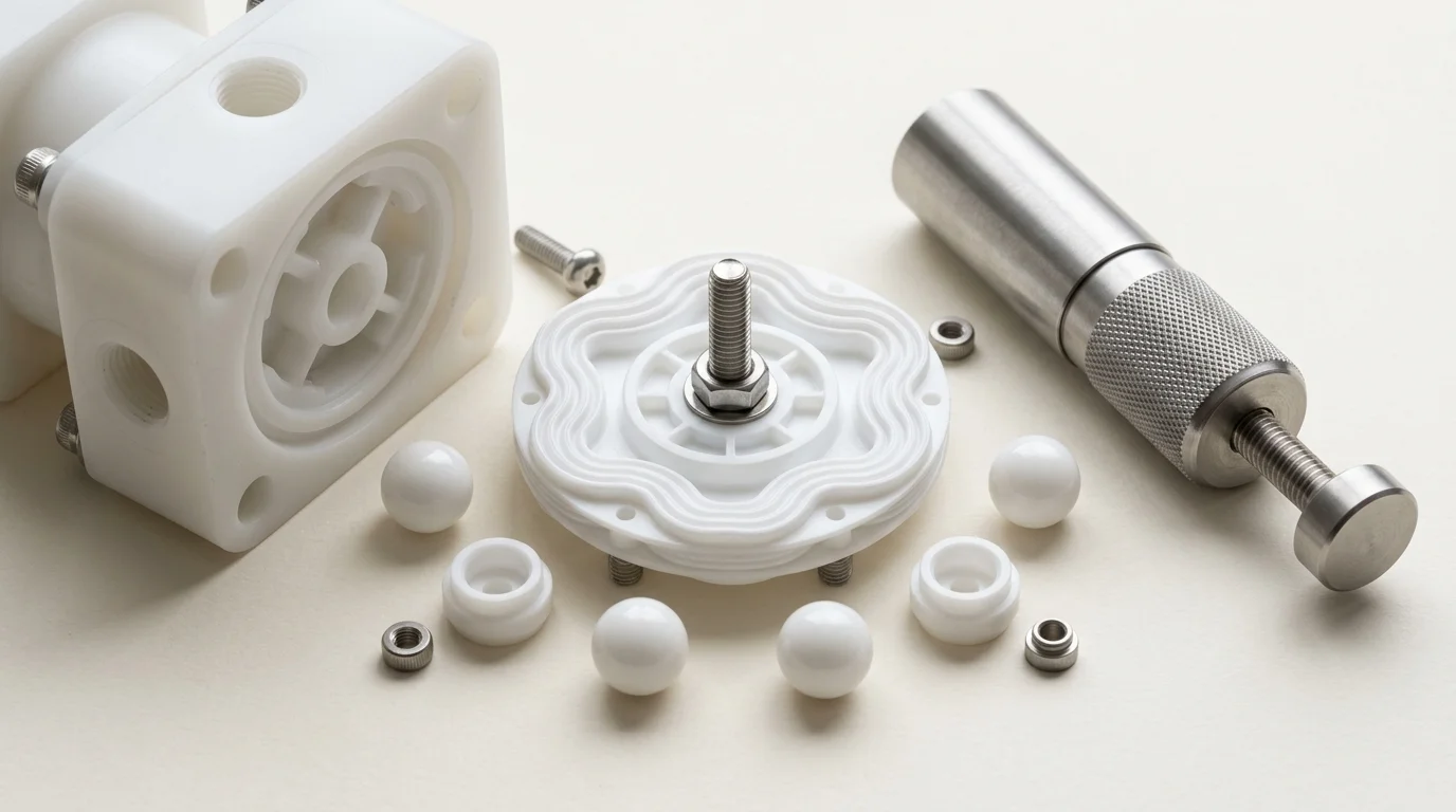
Dosing Pump Flow Rate Calculation for Chemical Metering: Sizing Math, Stroke Physics & Precision Metering Manual
A definitive chemical dosing calculation manual, positive displacement stroke displacement standard, and metering pump troubleshooting guide for process engineers, water treatment chemists, and ETP superintendents across Vatva GIDC, Narol, Odhav, Surat, and Gujarat.
Quick Answer
In the chemical synthesis complexes, textile dyehouses, reverse osmosis (RO) membrane desalination plants, and common effluent treatment plants (CETP) of Gujarat—spanning Ahmedabad (Vatva GIDC, Narol, Odhav), Surat, Ankleshwar, and Dahej—controlled-volume dosing pumps are vital for chemical metering. Whether dosing sodium hypochlorite (10%-12%) for disinfection, caustic soda (48%) for pH neutralization, ferric chloride (40%) for coagulation, or antiscalants into high-pressure RO feedwater, maintaining precise volumetric dosing accuracy (± 1.0%) is critical. Unlike dynamic centrifugal pumps whose flow rate fluctuates with system discharge pressure, positive displacement chemical dosing pumps deliver a fixed displacement volume per stroke. The primary governing equation is Q_L/h = V_stroke · N_strokes/min · 60 · \eta_vol. Sizing chemical dosing pumps requires determining the exact volumetric stroke displacement from plunger or diaphragm geometry, calculating target Parts Per Million (PPM) chemical injection concentrations based on main process flow and specific gravity, setting dual turndown controls (stroke length and stroking frequency), and eliminating check ball fouling in accordance with ISO 5199, ISO 2858, and DIN 24255 standards.
Key Takeaways
- Calculate Stroke Displacement Accurately. Use Q_L/h = [π· d_mm²] / [4] · S_mm · N_spm · \eta_vol × 6 × 10^-5 to compute maximum volumetric metering capacity.
- Master the Process PPM Dosage Formula. Calculate required reagent feed using Q_dosing (L/h) = [Q_water (m³/h) × C_target (PPM)] / [Chemical Concentration (%) × SG × 10,000].
- Maintain Minimum Discharge Backpressure (> 1.5 bar). Always install an adjustable backpressure valve to prevent siphoning and ensure positive check ball seating.
- Calibrate Regularly with a Drawdown Cylinder. Verify actual delivered flow across 25%, 50%, 75%, and 100% stroke settings to correct for viscosity and seat slip.
Introduction
Across Gujarat's industrial processing infrastructure—including the chemical intermediate plants of Vatva GIDC, Odhav, and Ankleshwar, the continuous textile dyehouses of Narol and Surat, and the large-scale petrochemical terminals of Dahej—controlled chemical metering is essential for reaction yield and environmental compliance.
Unlike centrifugal transfer pumps, chemical dosing pumps are positive displacement machines designed to inject precise micro-volumes of concentrated reagents against system pressure:
- The Metering Accuracy Imperative: In water treatment and chemical synthesis, dosing errors directly cause out-of-spec product batches, excessive chemical waste, or irreversible fouling of expensive RO membrane elements.
- The Concentration Calculation Challenge: Process engineers must continuously convert raw reagent percentage purity, solution specific gravity, and process water flow rates into exact liter-per-hour (L/h) dosing rates.
- The Hydraulic Pulsation Risk: Reciprocating plunger and diaphragm motion generates high acceleration head losses in long suction piping, inducing cavitation and check valve chatter unless properly mitigated.
- The Engineering Standard: Following ISO 5199, ISO 2858, and DIN 24255 standards—incorporating calibration drawdown cylinders, adjustable backpressure valves, and virgin PTFE diaphragms—ensures steady metering accuracy within ± 1.0%.
2. Master Chemical Metering & Dosing Sizing Matrix
Review the standard chemical metering ranges, liquid-end materials, and stroke frequency limits for chemical dosing pumps:
| Chemical Reagent Application | Typical Dosing Range | Liquid-End Material | Check Valve Ball Material | Recommended Stroking Speed |
|---|---|---|---|---|
| Sodium Hypochlorite (10%-12%) | 0.5 to 25 L/h | Solid PVDF / PTFE | Alumina Ceramic / Glass | < 100 strokes/min (Prevent outgassing) |
| Sulfuric Acid (98%) | 2.0 to 120 L/h | Virgin PTFE / PVDF | Silicon Carbide (SSiC) | 50 - 120 strokes/min |
| Caustic Soda (48% NaOH) | 5.0 to 250 L/h | SS316 / PTFE | SS316 / Silicon Carbide | 60 - 140 strokes/min |
| Ferric Chloride (40%) | 10 to 500 L/h | Polypropylene / PVDF | Alumina Ceramic | 60 - 120 strokes/min |
| RO Antiscalant Concentrate | 0.1 to 15 L/h | Pure PTFE / PVDF | Ruby / Sapphire / Ceramic | 40 - 100 strokes/min |
3. The Positive Displacement Physics, Stroke Math & Dosing Formulas
Positive Displacement Stroke Volume Equation (V_stroke = [π· d²] / [4] · S)
Theoretical displacement volume per stroke (V_stroke) of a reciprocating plunger or hydraulically actuated diaphragm is calculated as:
Interactive Chemical Dosing & Injection Rate Sizer
Live ISO 5199 / API 610 Dynamic EngineTo convert displacement into milliliters (mL) per stroke:
- Sizing Example: For a metering pump with a 32 mm plunger diameter and an adjustable stroke length of 6.0 mm:
Metric Volumetric Flow Rate Math (Q_L/h = V_disp · N · 60 · \eta_vol)
Continuous volumetric delivery rate (Q_L/h) in liters per hour is given by:
Where:
- d_mm is plunger or hydraulic diaphragm diameter (mm).
- S_mm is linear mechanical stroke length (mm).
- N_spm is stroking speed in strokes per minute (SPM).
- \eta_vol is volumetric efficiency (≈ 0.92 - 0.98 for clean water-like chemicals; ≈ 0.80 - 0.88 for viscous polymers).
- Sizing Calculation: At N = 100 SPM, S = 6.0 mm, d = 32 mm, and \eta_vol = 0.95:
Chemical Concentration & Process Water PPM Dosage Math
To calculate the required dosing pump flow rate (Q_dosing) in liters per hour to achieve a target chemical concentration (C_target) in Parts Per Million (PPM or mg/L) for a main process stream (Q_water):
- Real-World Chemical Plant Calculation:
- Main ETP wastewater flow Q_water = 150 m³/h. - Target chlorine dosage for disinfection C_target = 5.0 PPM. - Reagent: Commercial Sodium Hypochlorite solution with 10% available chlorine (Purity = 10%, SG = 1.16).
- The plant requires a chemical metering pump rated for 0 - 100 L/h, operating at 65% stroke capacity.
Turndown Ratio & Dual Control (Stroke Length vs Frequency) Dynamics
Dosing flow can be modulated using two independent mechanisms:
- Stroke Length Modulation: Manually adjusting the micrometer dial modifies plunger travel (S_mm), providing 10:1 turndown (10%-100%). Adjusting stroke length below 10% degrades volumetric accuracy due to check valve slip.
- Stroke Frequency Modulation: Modulating motor speed via VFD or electronic pulse pacing provides 10:1 speed turndown (10 - 100 SPM).
- Combining both controls provides a combined turndown range of 100:1, enabling high precision across wide process flow swings.
Hydraulic Pulsation & Acceleration Head Loss Math (h_a = [L · v · N · C] / [g · K])
Reciprocating positive displacement generates pulsing flow that creates acceleration head loss (h_a) in suction piping:
- If h_a is high, available suction pressure drops below vapor pressure, causing suction cavitation. Installing a suction pulsation dampener close to the pump liquid end reduces acceleration head losses by over 85%.
4. The 5 Critical Causes of Chemical Dosing Inaccuracy & Flow Decay
Cause 1: Suction / Discharge Check Valve Ball Seat Crystallization
- Mechanism: Sodium hypochlorite, caustic soda, or alum dries and forms hard mineral crystals on ceramic check valve seats.
- Symptoms: Dosing flow drops to near zero despite normal motor stroking; chemical bypasses back and forth across seats.
- Fix: Flush liquid end with hot condensate; inspect and clean ceramic ball seats; install dual ball check valve cartridges.
Cause 2: Siphoning & Free-Flow from Insufficient Discharge Backpressure
- Mechanism: Dosing liquid into an atmospheric open channel or vessel below the chemical storage tank level without backpressure valves.
- Symptoms: Chemical flows unmetered by gravity (siphoning); dosing rate exceeds micrometer setting by 200%-500%.
- Fix: Install an adjustable spring-loaded diaphragm backpressure valve set to minimum 1.5 to 2.0 bar.
Cause 3: Outgassing & Vapor Lock in Volatile Reagent Lines
- Mechanism: Sodium hypochlorite, hydrogen peroxide, or volatile acids decompose and release micro-bubbles during suction stroke.
- Symptoms: Gas bubbles compress inside dosing head without building pressure to lift discharge check ball; flow stops completely.
- Fix: Install automatic degassing liquid ends or route suction piping with continuous downward slope and zero high loops.
Cause 4: PTFE Diaphragm Fatigue, Creep & Elasticity Loss
- Mechanism: PTFE diaphragm undergoes millions of flex cycles under corrosive attack, developing micro-cracks or permanent stretch.
- Symptoms: Delivered stroke volume drops gradually over months; chemical leaks into intermediate oil chamber.
- Fix: Replace solid virgin PTFE diaphragm every 12 to 18 months during scheduled preventive maintenance overhauls.
Cause 5: High Viscosity Sluggish Ball Seating & Volumetric Slip
- Mechanism: Dosing viscous polymer flocculants (\nu > 500 cSt) with standard gravity check balls.
- Symptoms: Viscous fluid cushions ball descent, allowing significant liquid to slip back before the valve closes; volumetric efficiency drops < 60%.
- Fix: Install spring-loaded check balls or upsize check valve port diameters to accelerate positive seating.
5. Step-by-Step Dosing Pump Calibration & Maintenance SOPs
Execute this structured engineering protocol when calibrating, calculating, or troubleshooting chemical dosing pumps:
Phase 1: Drawdown Calibration Cylinder Measurement SOP
- Cylinder Lineup: Fill a transparent graduated calibration drawdown cylinder (100 - 1000 mL) with process reagent.
- Drawdown Timing: Isolate main chemical suction tank; open calibration cylinder valve; run pump for exactly 60 seconds timed with a stopwatch.
- Delivered Flow Calculation:
Phase 2: Stroke Length Micrometer Linearity Audit SOP
- Four-Point Calibration: Measure delivered flow at 25%, 50%, 75%, and 100% stroke length dial settings.
- Linearity Verification: Plot calibration curve; verify linear regression coefficient is R² ≥ 0.99.
Phase 3: Backpressure Valve Setting & Siphon Verification SOP
- Pressure Gauge Observation: Observe in-line discharge pressure gauge; adjust backpressure valve screw until gauge reads steady 1.5 to 2.0 bar.
- Zero Siphon Check: De-energize pump; verify zero chemical drips from injection quill under static head.
Phase 4: Check Valve Cartridge Inspection & Lapping SOP
- Cartridge Removal: Unscrew suction and discharge check valve cartridges.
- Ball & Seat Audit: Inspect ceramic balls and seats under magnification for pitting, scratches, or chemical deposits. Replace worn seats.
Phase 5: Dynamic Rotor Balancing to ISO 5199 Grade G2.5 SOP
- Dynamic Balancing: Dynamically balance high-speed motor and eccentric drive shaft on balancing machine.
- Balance Certification: Achieve residual unbalance < 1.0 g\cdotmm/kg conforming to ISO 5199 Grade G2.5.
Phase 6: Pressure Relief Valve & Pulsation Dampener Tuning SOP
- Relief Valve Setting: Set safety pressure relief valve to 1.15× maximum design working pressure.
- Dampener Nitrogen Pre-Charge: Pre-charge pulsation dampener bladder with dry nitrogen to 0.70× operating line pressure.
6. Materials of Construction, Metallurgy & Liquid-End Selection
Solid Virgin PTFE / PFA Molded Diaphragms
- Diaphragm Technology: Multi-layer composite solid virgin PTFE diaphragms backed with high-elasticity EPDM cores, providing universal chemical compatibility with concentrated acids, strong oxidizers, and hazardous solvents.
PVDF & Polypropylene Liquid Ends for Strong Acids & Alkalis
- Liquid-End Heads: Precision-machined solid PVDF and ultra-pure Polypropylene heads capable of operating up to 10 bar working pressure without stress cracking.
High-Purity Alumina Ceramic & Silicon Carbide Check Balls
- Valve Components: High-density 99.5% Alumina Ceramic and direct-sintered silicon carbide (SSiC) check balls and precision-lapped seats providing zero-leak shutoff and high wear resistance against abrasive slurries.
Hastelloy C-276 & SS316 Dosing Heads for Organic Solvents
- Metallic Liquid Ends: Investment cast SS316 and forged Hastelloy C-276 dosing heads for high-pressure injection (> 50 bar) and flammable organic solvents.
7. The Process Chemist's Dosing Calculation Decision Matrix
Follow this structured engineering guide when calculating and troubleshooting chemical dosing skids:
| Observed Dosing Discrepancy | Identified Root Cause | Mandatory Corrective Engineering Action | Verification Metric |
|---|---|---|---|
| Dosing flow 30% above dial setting | Siphoning through open discharge | Install / Tighten backpressure valve to 2 bar | Zero static gravity flow |
| Pump strokes; zero chemical delivered | Check ball stuck on crystallized seat | Flush with hot condensate; clean ceramic seat | ± 1% Drawdown accuracy |
| Flow drops sharply on hypochlorite | Vapor lock from gas decomposition | Install automatic degassing liquid-end head | Continuous bubble-free dosing |
| Delivered flow non-linear at low dial | Stroke length dial set < 15% | Increase stroke to 60%; reduce VFD speed | Linear flow response |
| Severe suction piping vibration | High acceleration head loss (h_a) | Install suction pulsation dampener close to head | Suction pressure stable |
8. Worked Gujarat ETP, RO & Chemical Plant Case Studies
Case 1: Vatva GIDC Chemical Synthesis Reactor Acid Dosing Calibration Fix
- Plant Context: An azo dye synthesis facility in Vatva GIDC dosing 98% sulfuric acid into batch reactors (Q = 35 L/h).
- Problem: Batch pH drifted randomly; acid consumption exceeded theoretical stoichiometry by 22%.
- Root Cause: Missing discharge backpressure valve allowed acid to siphon continuously by gravity whenever the supply tank was full.
- Action Plan: Teflow Pumps engineering team:
- Installed a PVDF adjustable diaphragm backpressure valve set to 2.2 bar. - Fitted a 500 mL transparent graduated drawdown calibration cylinder. - Dynamically balanced motor drive and calibrated stroke length linearity.
- Outcome: Stoichiometric acid dosing accuracy restored to ± 0.8%; raw sulfuric acid consumption reduced by 22%, saving over 4.2 lakh INR annually in raw chemical costs.
Case 2: Narol Continuous Textile Stenter Caustic Dosing Overhaul
- Plant Context: A textile processing mill in Narol dosing 48% NaOH into continuous fabric scouring ranges.
- Problem: Dosing pump check balls seized every 2 to 3 weeks due to caustic soda crystallization.
- Action Plan: Upgraded to dual-ball ceramic check valve cartridges with automated water flushing bypass.
- Outcome: Check valve maintenance intervals extended from 2 weeks to over 14 months.
Case 3: Odhav Effluent Treatment Plant Hypochlorite Metering Upgrade
- Plant Context: A common effluent treatment plant (CETP) in Odhav dosing 12% sodium hypochlorite for final effluent decolorization.
- Problem: Chronic vapor locking caused dosing to stop randomly during hot summer afternoons (42°C ambient).
- Action Plan: Installed an auto-degassing PVDF liquid-end dosing head with continuous vapor bleed back to supply tank.
- Outcome: Completely eliminated vapor locking; continuous plant decolorization compliance achieved.
Case 4: Surat Synthetic Weaving Mill RO Antiscalant Dosing Sizing
- Plant Context: A water desalination plant in Surat operating a 100 m³/h RO system requiring 3.0 PPM antiscalant.
- Problem: Membrane scaling occurred because an oversized pump operated at < 5% stroke length where metering linearity collapsed.
- Action Plan: Sized and installed a micro-flow PTFE diaphragm dosing pump operating at 60% stroke length (2.5 L/h).
- Outcome: Antiscalant dosing accuracy maintained within ± 0.5%; membrane cleaning frequency reduced by 65%.
Case 5: Ankleshwar GIDC Pharma Bulk Drug Reagent Metering Recovery
- Plant Context: A pharma synthesis plant in Ankleshwar GIDC metering hydrochloric acid into reaction vessels.
- Problem: Solid PTFE diaphragm failed every 4 months due to chemical fatigue.
- Action Plan: Upgraded to composite virgin PTFE multi-layer diaphragms with EPDM elastic cores and intermediate leak sensors.
- Outcome: Zero diaphragm ruptures over 18 operating months.
Case 6: Dahej PCPIR Petrochemical Wastewater Coagulant Skid Audit
- Plant Context: A petrochemical complex in Dahej PCPIR dosing 40% ferric chloride (Q = 200 L/h).
- Problem: Heavy acceleration head loss caused severe suction pipe rattling and check ball chatter.
- Action Plan: Installed a charging pulsation dampener with Viton bladder on suction header.
- Outcome: Pressure pulsations reduced by 88%; smooth, quiet metering operation restored.
9. Comprehensive Master Chemical Dosing Pump Maintenance Checklist
Execute this calibration and maintenance protocol to verify chemical dosing accuracy:
Chemical Dosing Pump Calibration & Performance Protocol
10. Summary & Specialized Dosing Pump Engineering Services in Gujarat & India
Calculating and optimizing chemical dosing pump flow rates—mastering positive displacement stroke displacement math, calculating process PPM reagent requirements, executing drawdown cylinder calibrations, tuning backpressure valves (> 1.5 bar), and dynamically balancing drive assemblies to ISO 5199 Grade G2.5 across Vatva GIDC, Narol, Odhav, Surat, Ankleshwar, and Dahej—conforming to ISO 5199, ISO 2858, and DIN 24255 standards—is the proven engineering standard for chemical process and water treatment reliability.
Partnering directly with an established Gujarat rotating machinery manufacturer provides chemical plant chemists, ETP managers, and water treatment specialists with immediate technical access to on-site dosing calibration teams, precision PTFE diaphragm skids, calibration cylinders, dynamic balancing facilities, and genuine spares dispatched directly from our Ahmedabad factory. Our technical engineers provide emergency on-site troubleshooting, turnkey pump overhauls, and complete dosing skid audits.
Teflow Pumps operates a specialized industrial machinery manufacturing and service facility in Ahmedabad, providing emergency chemical dosing pump overhauls, PTFE/PVDF diaphragm replacements, precision drawdown calibrations, dynamic balancing, and genuine rotating equipment spares across Gujarat and India conforming to ISO 5199, ISO 2858, DIN 24255, and IS 5120 standards.
- Direct Technical & Emergency Helpline: +91 98251 62709
- WhatsApp Technical Desk: Share process water flow rates (Q_m³/h), target chemical PPM requirements, chemical purity percentages, pump nameplate photos, or dosing error symptoms to wa.me/919825162709 for immediate technical review, dosage calculation, and formal quotation.
- Request an On-Site Dosing Skid Audit & Calibration: Contact our senior rotating equipment engineers for emergency plant surveys, calibration proposals, and formal quotation. Our engineering team conducts comprehensive thermal evaluations, verifies ISO 5199 criteria, provides precision on-site or workshop reconditioning, and dynamically balances overhauled hot oil pumps to ensure maximum uptime across Gujarat's textile and chemical processing mills. We provide rapid technical evaluations, on-site plant surveys, and formal quotes.
Related Reading
- Peristaltic pump flow rate calculation guide for dosing skids
- Industrial pump repair and overhaul services
- Teflon lined and chemical pumps overview
- Series vs parallel pumps for RO booster sizing guide
- Chemical pipe sizing and velocity limits guide
- ETP, CETP and wastewater sump pump overhaul services