
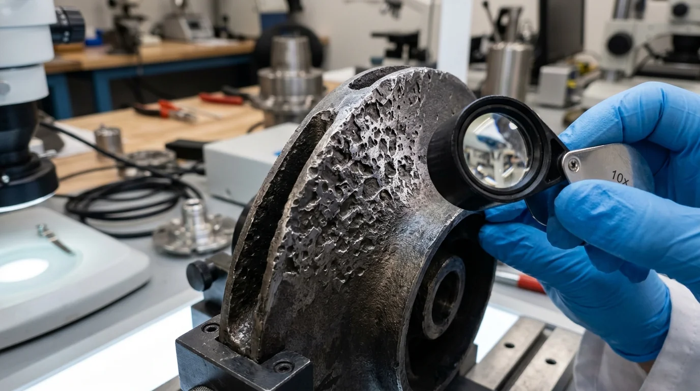
NPSHa Calculator: Check Suction Before Cavitation Hits: Fluid Mechanics Sizing & Overhaul Manual
A definitive hydraulic suction physics standard, Net Positive Suction Head Available (NPSHa) calculation manual, and centrifugal pump cavitation elimination guide for plant managers, process engineers, and rotating machinery reliability leads across Vatva GIDC, Narol, Odhav, Surat, and Gujarat.
Quick Answer
In the industrial manufacturing hubs, chemical processing plants, bulk drug synthesis facilities, and water treatment plants of Gujarat—spanning Ahmedabad (Vatva GIDC, Narol, Odhav), Surat, Ankleshwar, and Dahej—cavitation is the leading cause of premature mechanical seal failure and catastrophic impeller destruction. Preventing hydraulic cavitation requires precise calculation of Net Positive Suction Head Available (NPSHa) before pump commissioning. NPSHa measures the absolute hydraulic pressure energy available at the pump suction nozzle above the liquid's vapor pressure, calculated via the complete metric equation: NPSHa (meters) = [P_surface (bar) × 10.197] / [Specific Gravity] ± Z_static (m) - h_friction (m) - [P_vapor (bar) × 10.197] / [Specific Gravity]. To prevent vapor bubble formation, the plant suction system must maintain an engineering margin conforming to Hydraulic Institute (HI 9.6.1) and ISO 5199 standards, requiring NPSHa ≥ NPSHr + 1.0 meter (or NPSHa / NPSHr ≥ 1.20 - 1.50).
Key Takeaways
- Master the Metric NPSHa Formula. Calculate available suction head using NPSHa = h_atm ± h_static - h_friction - h_vapor.
- Model Liquid Vapor Pressure (P_vap). Recognize that higher fluid temperatures exponentially increase vapor pressure, rapidly destroying suction head.
- Maintain Minimum NPSH Safety Margins. Ensure NPSHa ≥ NPSHr + 1.0 meter under worst-case lowest liquid levels and highest temperatures.
- Eliminate Suction Piping Choke Points. Install eccentric reducers flat-on-top, minimize elbows within 5D of the suction flange, and clean strainers.
Introduction
Across Gujarat's industrial processing centers—including the high-temperature chemical synthesis corridors of Vatva GIDC, Narol, and Odhav, the pharmaceutical active ingredient reactors of Ankleshwar, and the petrochemical transfer lines of Dahej—pumping hot, volatile, or viscous liquids presents extreme suction challenges.
When liquid enters the suction eye of a rotating centrifugal pump impeller, fluid velocity accelerates, causing local static pressure to drop to its lowest point inside the machine:
- The Physics of Cavitation: If absolute pressure drops below the fluid's vapor pressure (P_local < P_vapor), the liquid instantly vaporizes, forming thousands of microscopic vapor bubbles.
- The Destructive Collapse: As these vapor bubbles travel into the higher-pressure regions of the impeller vanes, they collapse violently at supersonic micro-jet velocities (> 1000 m/s) with localized impact pressures exceeding 10,000 bar.
- The Mechanical Damage: This relentless bombardment gouges deep metal pits into impeller vanes, fractures mechanical seal faces within hours, and produces severe vibration and characteristic "pumping gravel" noise.
- The Engineering Standard: Following ISO 5199, ISO 2858, and Hydraulic Institute (HI 9.6.1) standards—mastering metric NPSHa calculations, determining fluid vapor pressure, optimizing suction piping geometry, and providing adequate NPSH margins—eliminates cavitation at its physical root.
2. Master NPSHa vs NPSHr & Cavitation Comparison Matrix
Review the governing mathematical formulas, physical definitions, and operating boundaries for Net Positive Suction Head parameters:
| Engineering Parameter | Definition & Metric Formula | Source & Control | Safe Operating Criterion | Failure Mode If Violated |
|---|---|---|---|---|
| NPSHa (Available) | NPSHa = h_surface ± Z - h_f - h_vap | Plant Suction Piping & Sump System | NPSHa ≥ NPSHr + 1.0 m | Suction starvation & cavitation |
| NPSHr (Required) | NPSHr = Head at 3% head drop (NPSH3) | Pump Impeller Geometry & Speed | Supplied on pump test curve | Pump capacity & head collapse |
| NPSH Margin Ratio | Ratio = (NPSHa) / (NPSHr) | Combined Hydraulic Design | ≥ 1.20 (Water), ≥ 1.50 (Chemical) | Intermittent cavitation erosion |
| Vapor Head (h_vap) | h_vap = [P_vapor (bar) × 10.197] / [SG] | Fluid Temperature & Chemistry | Lower is better (Cooler fluid) | Thermal cavitation spike |
| Suction Friction (h_f) | h_f = f · (L_equiv) / (D) · [v²] / [2g] | Pipe Diameter, Valves & Strainer | Keep v_suction ≤ 1.2 m/s | High dynamic head loss |
3. The Fluid Dynamics Physics & Suction Head Mathematical Derivations
Complete Metric NPSHa Equation (NPSHa = h_surface ± Z - h_f - h_vap)
Net Positive Suction Head Available (NPSHa) represents the total absolute head available at the center line of the pump suction impeller eye, minus the absolute vapor pressure head of the liquid:
Interactive Net Positive Suction Head (NPSHa) Sizer
Live ISO 5199 / API 610 Dynamic EngineSubstituting industrial engineering metric units:
Where:
- P_surface is the absolute pressure on the liquid surface in the suction vessel (in bar absolute; 1.013 bar for atmospheric open tanks).
- Specific Gravity (SG) is the ratio of liquid density to water density (ρ/ 1000).
- Z_static is the static liquid height above (+Z, flooded suction) or below (-Z, suction lift) the pump centerline in meters.
- h_friction is total friction and fitting head loss in the suction piping in meters.
- P_vapor is the absolute vapor pressure of the liquid at operating temperature (in bar absolute).
- Calculation Example: A chemical process pump in Vatva GIDC transfers 98% Sulfuric Acid (SG = 1.84) at 45°C from an atmospheric tank (P_surface = 1.013 bar) with liquid level 2.5 m above centerline (+Z = +2.5 m), suction pipe friction h_f = 0.60 m, and acid vapor pressure P_vap = 0.001 bar:
Thermodynamic Vapor Pressure Modeling (h_vap = [P_vap(T) × 10.197] / [SG])
Vapor pressure increases exponentially with fluid temperature per the Antoine Equation:
- Impact on Water: At 30°C, water vapor pressure is 0.042 bar (h_vap = 0.43 m). However, at 85°C, vapor pressure surges to 0.578 bar (h_vap = 5.89 m)—destroying over 5.4 meters of available suction head.
Darcy-Weisbach Suction Piping Friction Loss Math (h_f = f (L) / (D) [v²] / [2g])
Suction piping friction head loss combines pipe wall friction and localized fitting resistance:
- Engineering Rule: To minimize h_f, size suction piping such that fluid velocity v_suction ≤ 1.2 to 1.5 m/s, and select long-radius elbows and full-port isolation valves.
Static Liquid Level & Sump Elevation Head (± Z_static)
- Flooded Suction (+Z): Liquid level resides above pump suction centerline, adding positive hydrostatic pressure.
- Suction Lift (-Z): Liquid level resides below pump suction centerline, directly subtracting from available head. Maximum practical suction lift for water at sea level is 4.5 - 5.5 meters.
Hydraulic Institute (HI 9.6.1) NPSH Margin Ratio Standards ((NPSHa) / (NPSHr) ≥ 1.35)
The Hydraulic Institute establishes minimum recommended NPSH margins based on application severity:
- Clean Ambient Water: NPSHa ≥ NPSHr + 0.6 m (Ratio ≥ 1.15).
- Corrosive Chemicals / Hydrocarbons: NPSHa ≥ NPSHr + 1.2 m (Ratio ≥ 1.35).
- High-Temperature Boiler Feedwater: NPSHa ≥ NPSHr + 1.8 m (Ratio ≥ 1.50).
4. The 6 Critical Causes of Suction Head Deficit & Cavitation
Cause 1: Elevated Process Temperature & Liquid Vapor Pressure Spike
- Mechanism: Exothermic chemical reactions or hot condensate return elevate fluid temperature above design specs.
- Impact: Liquid vapor pressure rises dramatically, causing NPSHa to drop below NPSHr.
- Fix: Install suction heat exchanger/chiller or elevate suction supply tank height.
Cause 2: Suction Strainer Silt Clogging & High Delta-P
- Mechanism: Suction basket strainers or Y-strainers accumulate rust flakes, scale, and suspended solids.
- Impact: Differential pressure across strainer expands from 0.05 bar to > 0.50 bar (> 5 m head loss).
- Fix: Install duplex switchable basket strainers with differential pressure gauges and clean regularly.
Cause 3: Undersized Suction Piping & Eccentric Reducer Inversion
- Mechanism: Using pipe diameters smaller than pump suction nozzle or installing eccentric reducers with flat side down.
- Impact: High flow velocity creates massive friction losses, while inverted reducers trap air pockets that enter the impeller.
- Fix: Upsize suction pipe to 1.5× nozzle size and install eccentric reducers strictly flat on top.
Cause 4: High Fluid Specific Gravity Hydrostatic Head Suppression
- Mechanism: Pumping dense chemical acids (SG = 1.3 - 1.8) using atmospheric pressure head calculations based on water.
- Impact: Atmospheric pressure generates only 5.5 m head on dense acid vs 10.3 m on water.
- Fix: Re-calculate NPSHa using exact fluid specific gravity at operating concentration.
Cause 5: Suction Sump Vortexing & Atmospheric Air Ingestion
- Mechanism: Insufficient liquid submergence over suction pipe inlet creates swirling surface vortices.
- Impact: Core vortex draws atmospheric air directly into suction line, inducing two-phase flow and mechanical surging.
- Fix: Maintain minimum submergence (S_min = D · (1 + 2.3 · Fr)) or install anti-vortex baffle plates.
Cause 6: Off-BEP Operating Point Runout & High NPSHr
- Mechanism: Operating pump at 130% of rated Best Efficiency Point (BEP) flow rate due to low system head.
- Impact: Required NPSH (NPSHr) increases exponentially at high flow rates, overtaking available NPSHa.
- Fix: Throttle discharge valve to rated duty or trim impeller outer diameter.
5. Step-by-Step Field NPSHa Audit & Cavitation Troubleshooting SOPs
Execute this structured engineering protocol when evaluating, calculating, or troubleshooting suction cavitation:
Phase 1: Suction Pressure Gauge & Barometric Elevation Audit SOP
- Instrumentation: Install calibrated compound pressure/vacuum gauge on suction pipe tap (2D upstream of flange).
- Field Logging: Record actual suction pressure (P_gauge) during normal operation under lowest vessel liquid level.
- Absolute Suction Head Calculation:
Phase 2: Temperature Logging & Antoine Vapor Pressure Calculation SOP
- Temperature Measurement: Measure fluid temperature at suction nozzle using calibrated digital RTD thermometer.
- Vapor Head Calculation: Determine P_vapor from chemical thermodynamic tables; compute h_vapor = [P_vapor × 10.197] / [SG].
- Available Net Head: Compute live operating NPSHa = h_suction (abs) - h_vapor + [v²] / [2g].
Phase 3: Suction Piping Velocity (v ≤ 1.2 m/s) & Equivalent Length SOP
- Velocity Audit: Compute suction velocity v = [Q_m³/h] / [2827.43 · D_inner²].
- Piping Geometry Check: Confirm no short-radius elbows within 5D of suction flange; verify eccentric reducer is flat-on-top.
Phase 4: Impeller Eye Diameter & Vane Leading Edge Profiling SOP
- Impeller Inspection: Disassemble pump; inspect impeller eye diameter (D_eye) and vane leading edge profile.
- Cavitation Dressing: Dress eroded vane leading edges on precision grinder; restore smooth hydrodynamic bullet contour.
Phase 5: Dynamic Rotor Balancing to ISO 5199 Grade G2.5 SOP
- Dynamic Balancing: Mount refurbished impeller, shaft, and sleeve on balancing machine.
- Balance Certification: Achieve residual unbalance < 1.0 g\cdotmm/kg conforming to ISO 5199 Grade G2.5.
Phase 6: Laser Alignment, Acoustic Survey & Re-Commissioning SOP
- Laser Alignment: Align pump and motor shafts using dual-laser alignment tool (≤ 0.03 mm).
- Commissioning Survey: Restart pump; verify acoustic signature with vibration analyzer; confirm vibration < 1.80 mm/s RMS (Zone A) with zero cavitation noise.
6. Materials of Construction, Metallurgy & Cavitation Resistance
Duplex SS (2205) & Super Duplex SS (2507) Metallurgy
- Cavitation Pitting Resistance: High-yield-strength Duplex SS 2205 and Super Duplex SS 2507 provide superior resistance to micro-jet cavitation impact and chloride pitting compared to standard cast iron or 316 stainless steel.
Monolithic Direct-Sintered Silicon Carbide (SSiC) Bearings
- Bearing Stability: Monolithic direct-sintered SSiC sleeve bearings provide extreme hardness (> 2500 HV) and zero mechanical wear during momentary suction pressure dips.
Virgin PFA / Pure PTFE Linings for Corrosive Cavitation Protection
- Fluoropolymer Linings: Heavy-duty virgin PFA (3.5 - 5.0 mm) transfer-molded linings isolate casing ductile iron armor from corrosive chemical attack during two-phase fluid mixing.
Inducer Impellers for Low-NPSHr Applications
- Axial Inducers: Installing an axial-flow inducer ahead of the main centrifugal impeller eye lowers pump NPSHr by 40%-60%, enabling operation on critical low-NPSHa duties without cavitation.
7. The Process Engineer's NPSHa Sizing & Diagnostic Decision Matrix
Follow this structured engineering guide when calculating suction conditions and diagnosing cavitation:
| Calculated Margin (NPSHa - NPSHr) | Operating Cavitation Severity | Physical Observation | Corrective Engineering Action |
|---|---|---|---|
| > +2.0 meters | Zero Cavitation Risk | Quiet operation; smooth vibration | Optimal installation; continue operation |
| +1.0 to +2.0 meters | Acceptable for Clean Fluids | Minor acoustic hum at peak flow | Maintain clean suction strainers |
| +0.2 to +0.9 meters | Incipient Micro-Cavitation | Intermittent crackling noise | Lower fluid temperature or upsize suction pipe |
| < 0.0 meters (NPSHa < NPSHr) | Severe Classical Cavitation | Loud "gravel" noise; head collapse | Immediate shutdown; elevate suction supply tank |
8. Worked Gujarat Chemical, Textile & Industrial Plant Case Studies
Case 1: Vatva GIDC Chemical Synthesis Reactor Pump Cavitation NPSHa Fix
- Plant Context: A specialty dye intermediate plant in Vatva GIDC transferring hot acidic mother liquor (82°C, SG = 1.18, Q = 65 m³/h) from a crystallization vessel.
- Problem: Pump suffered violent cavitation noise; mechanical seal failed every 3 weeks; impeller vanes eroded within 4 months.
- Root Cause:
- At 82°C, liquid vapor pressure was P_vap = 0.51 bar (h_vap = 4.41 m). - Long 3-inch suction line generated 1.85 m friction loss. - Calculated NPSHa = 8.76 + 1.20 - 1.85 - 4.41 = 3.70 m, whereas pump NPSHr = 4.20 m (NPSHa Deficit = -0.50 m).
- Action Plan: Teflow Pumps engineering team:
- Replaced 3-inch suction line with a 4-inch line, reducing friction loss from 1.85 m to 0.42 m. - Installed an axial flow inducer on the pump impeller, reducing NPSHr from 4.20 m to 2.20 m. - Re-calculated NPSHa = 8.76 + 1.20 - 0.42 - 4.41 = 5.13 m (NPSH Margin = +2.93 m).
- Outcome: Completely eliminated cavitation gravel noise; mechanical seal and impeller operating continuously for over 22 months without failure.
Case 2: Narol Continuous Textile Stenter Caustic Pump Suction Head Upgrade
- Plant Context: A textile processing mill in Narol pumping hot caustic solution (70°C, Q = 90 m³/h).
- Problem: Clogged Y-strainer caused suction pressure drop, inducing severe cavitation and impeller erosion.
- Action Plan: Replaced Y-strainer with a low-loss duplex basket strainer and installed a differential pressure gauge.
- Outcome: Suction head increased by 1.4 m; eliminated cavitation completely.
Case 3: Odhav Effluent Treatment Plant Centrifugal Pump Cavitation Overhaul
- Plant Context: An industrial CETP in Odhav operating deep sump raw effluent transfer pumps.
- Problem: Sump level fluctuations caused severe vortex air entrainment and suction lift starvation.
- Action Plan: Installed anti-vortex baffle plates and lowered pump suction bell-mouth by 0.8 m.
- Outcome: Eliminated air ingress; vibration dropped from 8.5 mm/s to 1.2 mm/s RMS (Zone A).
Case 4: Surat High-Temperature Hot Condensate Return Pump NPSHa Recovery
- Plant Context: A synthetic yarn plant in Surat pumping hot boiler condensate at 96°C (P_vap = 0.87 bar).
- Problem: Inadequate static head above suction caused continuous flashing and boiler feed pump trips.
- Action Plan: Elevated condensate collection vessel by 2.2 meters and lagged suction pipe.
- Outcome: Added 2.2 m positive static head; zero flashing or tripping.
Case 5: Ankleshwar GIDC Pharma Reactor Vacuum Stripping Pump Overhaul
- Plant Context: A bulk drug synthesis plant in Ankleshwar GIDC pumping solvent from a vacuum distillation vessel (P_surface = 0.15 bar absolute).
- Problem: Severe cavitation occurred because vessel was under high vacuum.
- Action Plan: Sized and installed a canned motor sealless pump with ultra-low 1.1 m NPSHr.
- Outcome: Achieved stable solvent stripping under high vacuum without cavitation.
Case 6: Dahej PCPIR Petrochemical Acid Transfer NPSHa Re-Engineering
- Plant Context: A petrochemical facility in Dahej PCPIR transferring concentrated nitric acid (SG = 1.42).
- Problem: Undersized suction header caused high fluid shear and cavitation pitting on SS316 impellers.
- Action Plan: Upgraded suction piping to Duplex SS 2205 with 150 mm bore.
- Outcome: Restored positive NPSH margin of +2.4 m; extended impeller lifespan to over 36 operating months.
9. Comprehensive Master NPSHa Verification Checklist
Execute this suction hydraulics and cavitation prevention protocol before commissioning process pumps:
NPSHa Suction Sizing & Cavitation Elimination Protocol
10. Summary & Specialized Suction Audit Services in Gujarat & India
Calculating and optimizing Net Positive Suction Head Available—mastering thermodynamic vapor pressure math, sizing low-velocity suction piping, eliminating air-trapping reducer inversions, verifying NPSH safety margins, and dynamically balancing rotating assemblies to ISO 5199 Grade G2.5 across Vatva GIDC, Narol, Odhav, Surat, Ankleshwar, and Dahej—conforming to ISO 5199, ISO 2858, and DIN 24255 standards—is the proven engineering standard for eliminating cavitation and ensuring continuous plant uptime.
Partnering directly with an established Gujarat rotating machinery manufacturer provides chemical plant managers, process engineers, and rotating equipment specialists with immediate technical access to on-site suction diagnostic teams, ultrasonic flow meters, precision vacuum/pressure logging instrumentation, dynamic balancing facilities, and genuine spares dispatched directly from our Ahmedabad factory. Our technical engineers provide emergency on-site troubleshooting, turnkey pump overhauls, and complete suction header re-engineering.
Teflow Pumps operates a specialized industrial machinery manufacturing and service facility in Ahmedabad, providing emergency centrifugal pump overhauls, low-NPSHr impeller retrofits, axial inducer fabrication, dynamic balancing, laser alignment, and genuine rotating equipment spares across Gujarat and India conforming to ISO 5199, ISO 2858, DIN 24255, and IS 5120 standards.
- Direct Technical & Emergency Helpline: +91 98251 62709
- WhatsApp Technical Desk: Share suction piping drawings, fluid operating temperatures (°C), static liquid elevations (Z_static), suction gauge readings, or cavitation noise recordings to wa.me/919825162709 for immediate technical review, NPSHa calculation, and formal quotation.
- Request an On-Site Suction Piping & NPSHa Audit: Contact our senior rotating equipment engineers for emergency plant surveys, NPSHa audit proposals, and formal quotation. Our engineering team conducts comprehensive thermal evaluations, verifies ISO 5199 criteria, provides precision on-site or workshop reconditioning, and dynamically balances overhauled hot oil pumps to ensure maximum uptime across Gujarat's textile and chemical processing mills. We provide rapid technical evaluations, on-site plant surveys, and formal quotes.
Related Reading
- Total head calculation for pumps: static lift and pipe friction loss guide
- Industrial pump repair and overhaul services
- Teflon lined and chemical pumps overview
- Series vs parallel pumps for RO booster sizing guide
- Chemical pipe sizing and velocity limits guide
- ETP, CETP and wastewater sump pump overhaul services