
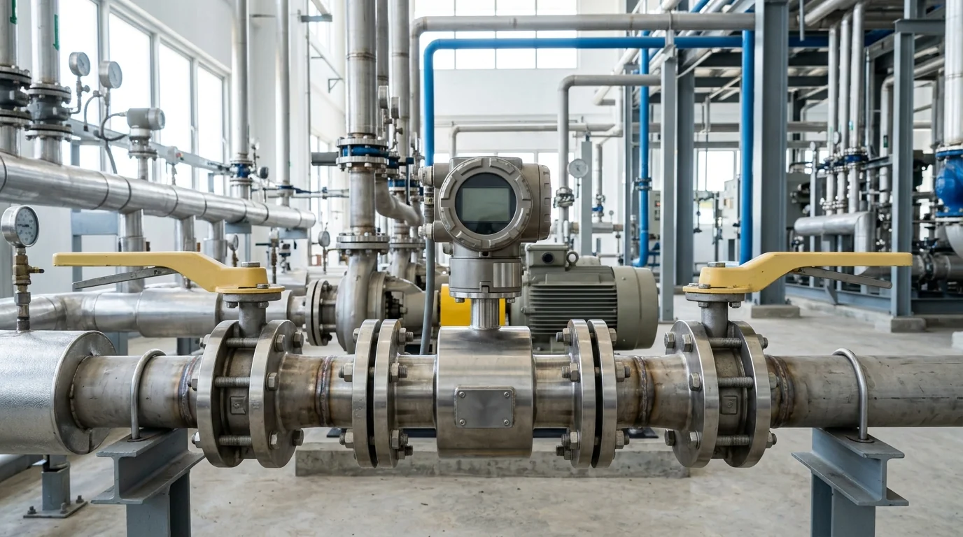
Pump Flow Rate Calculator & Formula for Chemical Plants: Sizing Math, Continuity Equations & Flow Loss Diagnostic Manual
A definitive fluid mechanics engineering guide, hydraulic flow rate mathematical standard, and pump capacity troubleshooting manual for process engineers, plant maintenance superintendents, and utility managers across Vatva GIDC, Narol, Odhav, Surat, and Gujarat.
Quick Answer
In the industrial manufacturing hubs, specialty chemical synthesis plants, pharmaceutical bulk drug units, and effluent treatment facilities of Gujarat—spanning Ahmedabad (Vatva GIDC, Narol, Odhav), Surat, Ankleshwar, and Dahej—accurate calculation and monitoring of centrifugal pump flow rate (Q) is fundamental to process stability. Whether transferring sulfuric acid (98%), hydrochloric acid (33%), caustic soda (48%), or circulating high-temperature organic media, process engineers must frequently verify delivered flow against pump performance curves. The core governing relationship is the hydraulic continuity equation Q = v · A, where flow rate equals the product of fluid velocity and cross-sectional pipe area. In practical plant metric units, Q_m³/h = 0.002827 · (d_mm)² · v_m/s. When field flow meters are absent, delivered flow rate can be precisely determined from suction and discharge pressure gauge readings via the pump head-capacity equation H = [P_discharge - P_suction] / [ρ· g]. Over time, unexplained flow degradation (often dropping by 20%-40%) indicates internal mechanical wear—such as doubled impeller wear ring clearances, vane erosion, suction line throttling, or air ingress. Sizing, calculating, and troubleshooting chemical pump flow rates requires strict engineering rigor conforming to ISO 5199, ISO 2858, and DIN 24255 standards.
Key Takeaways
- Master the Metric Continuity Formula. Use Q_m³/h = 0.002827 · (d_mm)² · v_m/s to calculate volumetric flow rate directly from pipe inner diameter and fluid velocity.
- Maintain Recommended Line Velocities. Size chemical suction lines for 1.0 to 1.8 m/s to prevent cavitation; size discharge lines for 2.0 to 3.0 m/s.
- Calculate Flow from Differential Pressure Gauges. Determine actual operating point by mapping differential head (ΔH = [ΔP] / [ρ· g]) onto the manufacturer's certified pump curve.
- Inspect Wear Ring Clearances During Flow Decay. A doubling of internal radial wear ring clearance (> 0.60 mm) bypasses up to 15% of delivered flow back to suction.
Introduction
Across Gujarat's industrial landscape—including the basic chemical and dye intermediate synthesis hubs of Vatva GIDC, Odhav, and Ankleshwar, the continuous textile processing belts of Narol and Surat, and the petrochemical complexes of Dahej—centrifugal pumps are the primary equipment for transferring corrosive liquids, hazardous solvents, and effluent slurries.
Accurate flow rate sizing and continuous flow monitoring are vital for plant economics, chemical reaction stoichiometry, and equipment reliability:
- The Hydraulic Sizing Dilemma: Undersized pumps fail to deliver required reactor feed rates, causing process bottlenecks. Oversized pumps operate far to the left of their Best Efficiency Point (BEP), generating high radial bearing thrust, internal recirculation, and premature seal failure.
- The Diagnostic Power of Pressure Gauges: In plants without dedicated in-line electromagnetic or ultrasonic flow meters, calibrated suction and discharge pressure gauges serve as an accurate, low-cost flow measurement tool when mapped against certified factory head-capacity curves.
- The Mechanical Degradation Footprint: When a chemical pump's flow drops gradually over months of service, internal wear ring erosion, chemical leaching, or impeller vane thinning is almost always the root cause.
- The Engineering Standard: Following ISO 5199, ISO 2858, and DIN 24255 standards—maintaining optimal pipe velocities, calculating Darcy friction losses, and verifying mechanical wear clearances—guarantees maximum hydraulic efficiency and process reliability.
2. Master Chemical Pump Flow Rate & Pipe Velocity Matrix
Review the standard pipe sizing guidelines, fluid velocity boundaries, and flow conversion factors for chemical process pumps:
| Nominal Pipe Size (NB) | Inner Diameter (d_inner) | Suction Flow at 1.5 m/s | Discharge Flow at 2.5 m/s | Typical Chemical Service Duty |
|---|---|---|---|---|
| DN25 (1-inch NB) | 27.0 mm | 3.1 m³/h | 5.2 m³/h | Acid dosing / Reagent metering |
| DN50 (2-inch NB) | 52.5 mm | 11.7 m³/h | 19.5 m³/h | Reactor transfer / Solvent charging |
| DN80 (3-inch NB) | 77.9 mm | 25.7 m³/h | 42.9 m³/h | Tanker unloading / Bulk chemical feed |
| DN100 (4-inch NB) | 102.3 mm | 44.4 m³/h | 74.0 m³/h | Effluent transfer / Utility cooling |
| DN150 (6-inch NB) | 154.1 mm | 100.8 m³/h | 168.0 m³/h | ETP main feed / Bulk acid circulation |
3. The Fluid Mechanics Physics, Continuity Math & Sizing Equations
Continuity Equation & Metric Flow Conversion (Q = v · A)
Volumetric flow rate (Q) through a closed circular conduit is derived from the principle of conservation of mass:
Interactive Engineering Hydraulic Sizer
Live ISO 5199 / API 610 Dynamic EngineTo convert directly into standard industrial plant units of cubic meters per hour (m³/h) with pipe inner diameter (d) in millimeters (mm) and fluid velocity (v) in meters per second (m/s):
- Sizing Example: For a DN80 Schedule 40 carbon steel or PTFE-lined pipe with inner diameter d = 77.9 mm running at a recommended chemical velocity v = 1.5 m/s:
Differential Pressure to Total Dynamic Head Equation (H = [ΔP] / [ρ· g])
When flow meters are absent in the field, total dynamic head (H) is calculated from pressure gauge readings:
Where:
- P_discharge and P_suction are measured pressures in Pascals (Pa). Note: 1.0 bar = 100,000 Pa = 100 kPa.
- ρ_liquid is liquid specific density (kg/m³). For 98% sulfuric acid, ρ≈ 1840 kg/m³; for water, ρ≈ 1000 kg/m³.
- g = 9.81 m/s² (acceleration due to gravity).
- Practical Plant Formula for Head:
- Example: A pump circulating 98% sulfuric acid (SG = 1.84) develops a differential pressure ΔP = 3.5 bar:
Pump Head-Capacity Curve Mapping Math (H = H_0 - k · Q²)
Centrifugal pump performance curves typically follow a parabolic head-flow relationship:
- Process engineers can map measured differential head (H_actual) directly onto the certified manufacturer test curve to determine instantaneous flow rate (Q_actual) within ± 3% accuracy.
Darcy-Weisbach Piping Friction Head Loss Math (h_f = f · (L) / (D) · [v²] / [2g])
Friction head loss (h_f) across the piping circuit is given by:
- Where f is friction factor derived from the Colebrook-White equation. As pipe scale and corrosion increase relative roughness (\varepsilon / D), friction losses increase, steepening the system curve and reducing delivered pump flow.
Hydraulic Power & Brake Horsepower Equation (P_hyd = [Q · H · ρ· g] / [3600])
Hydraulic power (P_hydraulic) transferred to the fluid is:
Brake Horsepower required from the electric motor:
4. The 6 Primary Causes of Unexplained Flow Loss in Chemical Pumps
Cause 1: Internal Wear Ring Clearance Degradation & Bypass
- Mechanism: Abrasive particles or corrosive chemical attack erode the close-running radial clearance between impeller neck and casing wear ring.
- Damage: Initial clearance (0.25 mm) expands to > 0.75 mm; high-pressure discharge liquid bypasses continuously back into the suction eye, reducing external delivered flow by 15%-25%.
- Fix: Replace worn wear rings or machine impeller shroud to restore OEM radial clearance (0.20 - 0.30 mm).
Cause 2: Suction Strainer Cake Build-up & Severe Throttling
- Mechanism: Chemical crystallites, polymer skins, or ETP fibers blind the suction basket strainer mesh.
- Damage: Suction line pressure drops sharply into deep vacuum (< -0.4 bar); NPSHa plunges below NPSHr, inducing vapor cavitation and collapsing delivered flow.
- Fix: Clean suction strainer basket regularly or install dual duplex strainers with differential pressure gauges.
Cause 3: Entrained Air / Gas Ingress Through Mechanical Seal or Suction Flange
- Mechanism: Sub-atmospheric suction conditions pull ambient air through loose flange gaskets or damaged mechanical seal bellows.
- Damage: Gas bubbles accumulate at the low-pressure center of the impeller eye; just 2% entrained air by volume reduces pump flow by up to 10%; 4% air causes complete air-binding.
- Fix: Torque suction flange bolts, replace damaged spiral-wound Grafoil gaskets, and maintain positive seal barrier fluid pressure.
Cause 4: Cavitation Vapor Locking at Impeller Eye
- Mechanism: Pumping volatile solvents (acetone, methanol, toluene) near their bubble point without adequate static suction head.
- Damage: Liquid flashes into vapor bubbles at the blade leading edges, choking the impeller throat and causing acoustic rattling and flow loss.
- Fix: Increase suction tank liquid level, sub-cool the liquid, or lower pump elevation to restore positive NPSH margin.
Cause 5: Reverse Three-Phase Motor Rotation
- Mechanism: Incorrect wiring phase sequence (e.g., swapping R and B leads during maintenance electrical reconnect).
- Damage: Centrifugal impeller still generates forward flow and head, but at only 40%-50% of rated capacity and severely degraded efficiency.
- Fix: Verify motor rotational arrow on pump casing; swap any two power leads in motor terminal box to reverse direction.
Cause 6: High Viscosity Fluid Flow De-Rating
- Mechanism: Pumping cold resins, heavy polyols, or concentrated caustic solutions (\nu > 50 cSt) with a pump selected for water.
- Damage: Viscous boundary layer drag severely flattens the H-Q curve, reducing delivered flow rate by 20%-50% and spiking motor amperage.
- Fix: Apply Hydraulic Institute (HI 9.6.7) viscosity correction factors and upsize impeller or motor drive rating.
5. Step-by-Step Chemical Pump Flow Measurement & Diagnostic SOPs
Execute this structured engineering protocol when testing, calculating, or troubleshooting pump flow rates in chemical plants:
Phase 1: Dual Pressure Gauge Differential Head Logging SOP
- Gauge Calibration: Install calibrated glycerine-filled pressure gauges on suction (P_s) and discharge (P_d) gauge taps.
- Differential Head Calculation: Convert differential pressure (ΔP = P_d - P_s) into dynamic head (H = [ΔP] / [ρ· g]). Map head onto pump curve to verify operating flow.
Phase 2: Ultrasonic Transit-Time Flow Meter Audit SOP
- Transducer Setup: Mount non-invasive ultrasonic clamp-on transducers on a straight pipe section (> 10D upstream, > 5D downstream of fittings).
- Flow Velocity Logging: Measure real-time volumetric flow (Q_m³/h) and fluid linear velocity (v_m/s); compare directly with calculated theoretical continuity flow.
Phase 3: Suction Line Vacuum & Strainer Differential Check SOP
- Suction Vacuum Measurement: Log suction gauge pressure under running load. Confirm suction pressure satisfies minimum NPSHa requirements.
- Strainer Delta-P Check: Verify pressure drop across suction strainer is < 0.15 bar. Clean mesh basket if pressure drop exceeds threshold.
Phase 4: Impeller Wear Ring Metrology & Clearance Audit SOP
- Internal Metrology: Dismantle pump rotating assembly in workshop; measure impeller wear ring OD and casing wear ring ID using inside micrometers.
- Clearance Verification: Confirm diametrical clearance is < 0.35 mm. If clearance exceeds 0.60 mm, replace wear rings to eliminate internal bypass.
Phase 5: Dynamic Rotor Balancing to ISO 5199 Grade G2.5 SOP
- Dynamic Balancing: Mount assembled impeller, shaft, and keys on dynamic balancing machine.
- Balance Certification: Achieve residual unbalance < 1.0 g\cdotmm/kg conforming to ISO 5199 Grade G2.5.
Phase 6: Laser Hot Alignment Verification & Re-Commissioning SOP
- Precision Alignment: Align pump and motor shafts using dual-laser alignment tool; achieve angular and parallel concentricity ≤ 0.03 mm.
- Flow Commissioning: Start pump against throttled discharge valve; verify full flow, motor current, and vibration < 1.80 mm/s RMS (Zone A).
6. Materials of Construction, Metallurgy & Corrosion Resistance
Virgin PFA / FEP Fluoropolymer Linings for Corrosive Acids
- Wet-End Wetted Components: Solid transfer-molded virgin PFA (3.5 - 5.0 mm wall thickness) permanently anchored with dovetail grooves to ductile iron armors, impervious to concentrated HCl, H_2SO_4, and hot chlorinated organics up to 180°C.
Solid PVDF & Ultra-Pure Polypropylene for Chemical Transfer
- Thermoplastic Construction: High-density Polyvinylidene Fluoride (PVDF) and Polypropylene (PP) casings providing excellent chemical resistance and smooth internal surface finishes that minimize boundary layer friction head loss.
SS316, Hastelloy C-276 & Titanium Alloys
- High-Alloy Metallurgy: Investment cast SS316, Hastelloy C-276, and Titanium Grade 2 for corrosive chemical synthesis, high-pressure organic solvent pumping, and high-temperature thermal fluids.
Monolithic Direct-Sintered Silicon Carbide (SSiC) Seal Faces
- Mechanical Seal Technology: Pure monolithic direct-sintered silicon carbide (SSiC) rotating and stationary faces offering near-diamond hardness (2800 HV), universal chemical resistance, and zero thermal deformation.
7. The Process Engineer's Flow Calculation Decision Matrix
Follow this structured engineering guide when evaluating delivered flow rates in chemical plants:
| Observed Flow Phenomenon | Dominant Diagnostic Indicator | Confirmed Root Cause | Mandatory Corrective Engineering Action |
|---|---|---|---|
| Delivered flow 30% below curve | Differential pressure normal; low flow | Internal wear ring clearance enlarged | Replace casing and impeller wear rings |
| Flow collapses after 15 minutes | Suction vacuum spikes (< -0.4 bar) | Suction basket strainer blinding | Clean or upsize suction strainer basket |
| Flow and head both at 50% | Motor current low; pump runs smooth | Reverse three-phase motor rotation | Swap two power leads in motor terminal box |
| Rattling noise; erratic pressure | NPSHa < NPSHr; vapor bubbles | Suction cavitation / Solvent flashing | Elevate suction feed tank liquid level |
| Flow drops on high viscosity oil | High motor current; low discharge head | Viscous boundary layer disc drag | Apply Hydraulic Institute viscosity de-rating |
8. Worked Gujarat Chemical, Pharmaceutical & ETP Plant Case Studies
Case 1: Vatva GIDC Chemical Synthesis Reactor Acid Transfer Flow Loss Overhaul
- Plant Context: An azo dye synthesis facility in Vatva GIDC operating a 45 m³/h, 3.2 bar PFA-lined magnetic drive chemical pump transferring 33% HCl.
- Problem: Delivered flow rate dropped from 45 m³/h to 28 m³/h over 8 months, bottlenecking acid charging cycles into main reaction vessels.
- Root Cause: Abrasive slurry crystallites had eroded the internal silicon carbide thrust bearings and impeller eye wear ring, increasing internal radial bypass clearance from 0.25 mm to 0.82 mm.
- Action Plan: Teflow Pumps service team:
- Overhauled pump rotating element in our Ahmedabad workshop. - Replaced worn casing wear ring and installed new precision-machined monolithic SSiC bearings. - Re-calculated suction piping head losses and dynamically balanced rotor to ISO 5199 Grade G2.5.
- Outcome: Delivered flow rate fully restored to 46.2 m³/h at design head; reactor charging cycle time reduced by 38%; zero maintenance downtime over 20 consecutive operating months.
Case 2: Narol Continuous Textile Stenter Chemical Dosing Sizing Fix
- Plant Context: A textile processing mill in Narol operating chemical dosing pumps for fabric finishing baths.
- Problem: Over-sized pump operated far to the left of BEP (Q = 2.0 m³/h on a 15 m³/h pump), causing rapid seal failure.
- Action Plan: Re-sized pump using metric continuity math and replaced with a correctly sized DN25 PFA-lined chemical pump.
- Outcome: Operating point shifted directly to 85% BEP; mechanical seal life extended from 6 weeks to over 24 months.
Case 3: Odhav Effluent Treatment Plant Centrifugal Pump Flow Restoration
- Plant Context: A common effluent treatment plant (CETP) in Odhav pumping neutralized acidic wastewater.
- Problem: Centrifugal pump flow dropped by 45% due to severe fibrous sludge blinding on the suction foot valve strainer.
- Action Plan: Removed restrictive foot valve; installed a self-priming chemical pump with top-flat eccentric reducer and duplex basket strainer.
- Outcome: Restored full 85 m³/h flow capacity; suction vacuum stabilized at -0.10 bar.
Case 4: Surat Specialty Chemical Bulk Acid Transfer Rate Upgrade
- Plant Context: A specialty chemical plant in Surat transferring 98% sulfuric acid from road tankers to bulk storage.
- Problem: Transfer took 2.5 hours per tanker instead of design 45 minutes.
- Action Plan: Audited piping velocity (v = 3.8 m/s in undersized DN50 pipe); upgraded suction line to DN80 Schedule 40 PTFE-lined pipe.
- Outcome: Friction head loss dropped by 72%; flow rate increased to 65 m³/h; tanker unloading time reduced to 42 minutes.
Case 5: Ankleshwar GIDC Pharma Intermediate Solvent Loop Recovery
- Plant Context: A bulk drug facility in Ankleshwar GIDC circulating methanol at 45°C.
- Problem: Solvent vaporized in suction line, choking impeller eye and reducing delivered flow by 50%.
- Action Plan: Re-routed suction piping with continuous downward slope and elevated solvent supply vessel by +2.2 meters.
- Outcome: Increased NPSHa by +0.28 bar; completely eliminated vapor cavitation and restored full flow.
Case 6: Dahej PCPIR Petrochemical Caustic Circulation Audit
- Plant Context: A petrochemical processing unit in Dahej PCPIR circulating 48% NaOH at 60°C (SG = 1.51).
- Problem: Motor tripped on overload during winter startups when caustic viscosity spiked.
- Action Plan: Recalculated hydraulic power requirements taking into account temperature-viscosity curves; upgraded to a higher torque motor.
- Outcome: Achieved reliable, trip-free year-round circulation at design 120 m³/h capacity.
9. Comprehensive Master Chemical Pump Flow Verification Checklist
Execute this hydraulic calculation and mechanical verification protocol to verify chemical pump flow rates:
Chemical Pump Flow Rate Calculation & Performance Protocol
10. Summary & Specialized Pump Sizing Services in Gujarat & India
Calculating and optimizing chemical pump flow rates—mastering hydraulic continuity equations, maintaining optimal piping velocities (1.0 - 1.8 m/s suction), mapping differential pressure gauge readings onto performance curves, diagnosing internal wear ring clearances, and dynamically balancing rotating assemblies to ISO 5199 Grade G2.5 across Vatva GIDC, Narol, Odhav, Surat, Ankleshwar, and Dahej—conforming to ISO 5199, ISO 2858, and DIN 24255 standards—is the proven engineering standard for process plant reliability.
Partnering directly with an established Gujarat rotating machinery manufacturer provides chemical process engineers, pharmaceutical maintenance superintendents, and utility managers with immediate technical access to on-site hydraulic audit teams, ultrasonic flow meters, pressure diagnostic manifolds, dynamic balancing facilities, and genuine spares dispatched directly from our Ahmedabad factory. Our technical engineers provide emergency on-site troubleshooting, turnkey pump overhauls, and complete hydraulic loop audits.
Teflow Pumps operates a specialized industrial machinery manufacturing and service facility in Ahmedabad, providing emergency chemical pump overhauls, PFA/PVDF pump sizing calculations, precision laser alignment, dynamic balancing, custom impeller casting, and genuine rotating equipment spares across Gujarat and India conforming to ISO 5199, ISO 2858, DIN 24255, and IS 5120 standards.
- Direct Technical & Emergency Helpline: +91 98251 62709
- WhatsApp Technical Desk: Share pipe diameters (d_mm), suction and discharge pressure readings (P_s, P_d), fluid specific gravity (SG), pump nameplate photos, or flow deficit symptoms to wa.me/919825162709 for immediate technical review, hydraulic calculation, and formal quotation.
- Request an On-Site Hydraulic Flow Audit & Pump Overhaul: Contact our senior rotating equipment engineers for emergency plant surveys, flow sizing proposals, and formal quotation. Our engineering team conducts comprehensive thermal evaluations, verifies ISO 5199 criteria, provides precision on-site or workshop reconditioning, and dynamically balances overhauled hot oil pumps to ensure maximum uptime across Gujarat's textile and chemical processing mills. We provide rapid technical evaluations, on-site plant surveys, and formal quotes.