
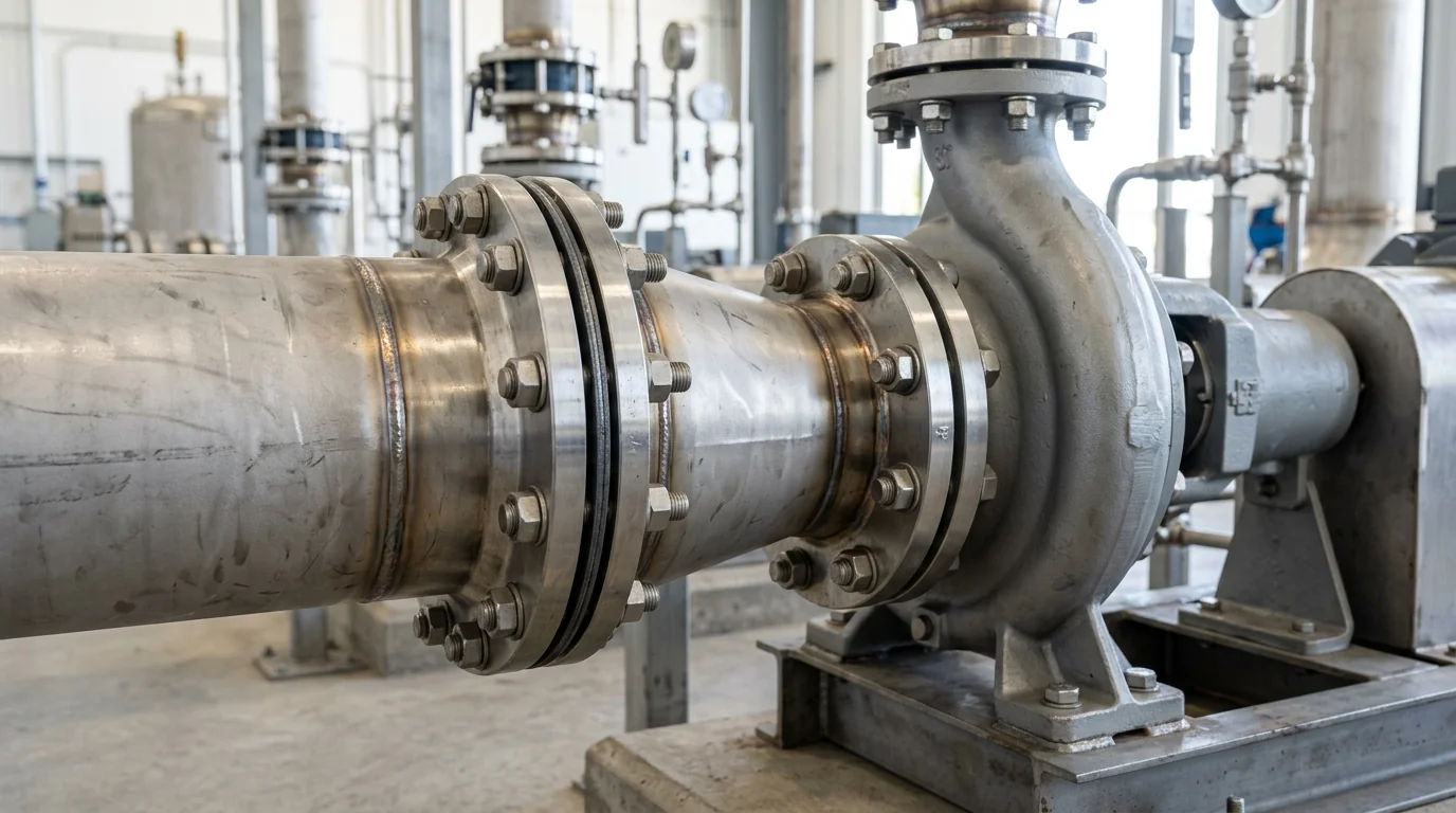
Suction Piping Rules That Protect Your NPSH Margin: Hydraulic Layout, Reducer Geometry & Cavitation Prevention Standard
A definitive process piping layout manual, suction hydraulic engineering standard, and Net Positive Suction Head (NPSH) protection guide for chemical process engineers, piping design consultants, and plant utility superintendents across Ahmedabad, Vatva, Ankleshwar, Dahej, and Gujarat.
Quick Answer
In the aggressive chemical manufacturing corridors, bulk solvent recovery units, and pharmaceutical synthesis plants of Gujarat—spanning Ahmedabad (Vatva, Naroda, Odhav), Ankleshwar GIDC, Dahej PCPIR, and Vapi—centrifugal process pumps frequently fail due to destructive suction cavitation. Maintenance teams often blame the pump manufacturer or assume inadequate suction head, but forensic hydraulic audits reveal that over 80% of chronic cavitation failures stem directly from improper suction piping layout. Common installation errors—such as undersized suction lines generating excessive friction (v > 2.0 m/s), concentric reducers that trap vapor pockets, short-radius elbows installed directly on the suction flange causing severe velocity profile distortion, and inadequate sump submergence that induces air-entraining vortices—destroy available Net Positive Suction Head (NPSH_a), plunging it far below pump NPSH_r. Implementing engineered suction piping rules conforming to ISO 5199, ISO 2858, IS 5120, and IS 1520 standards—enforcing low fluid velocities (0.6 - 1.2 m/s), providing a minimum 5 - 10× D undisturbed straight pipe run, using flat-on-top eccentric reducers, and installing Hydraulic Institute vortex breakers—guarantees a safe NPSH margin (NPSH_a - NPSH_r ≥ 1.0 m) and extends mechanical seal and impeller life beyond 40,000 continuous hours.
Key Takeaways
- Limit Suction Line Velocity to 0.6 - 1.2 m/s. Sizing suction lines one nominal size larger than the pump nozzle minimizes friction head loss.
- Enforce a 5 - 10× D Straight Run Before the Suction Flange. Prevent velocity profile distortion, flow separation, and uneven impeller vane loading.
- Install Flat-on-Top Eccentric Reducers in Horizontal Lines. Eliminate air and vapor pockets that form in concentric reducers and trigger cavitation bursts.
- Maintain Minimum Sump Submergence to Prevent Surface Vortices. Ensure submergence depth exceeds S_min = D + 0.574 [Q] / [√(g D³)] to block air ingestion.
Introduction
Across Gujarat's prominent chemical processing zones—centered in Ahmedabad (Vatva, Naroda, Odhav), Ankleshwar GIDC, Dahej PCPIR, and Vapi—centrifugal process pumps handle volatile, hot, and aggressive chemicals such as chlorinated solvents, boiling organics, and concentrated mineral acids.
Process design engineers, piping layout draftsmen, and maintenance superintendents face recurring cavitation failures:
- The Concentric Reducer Mistake: Installing a standard concentric reducer on a horizontal suction line creates a high point where dissolved gases and vapors accumulate. When an accumulated vapor bubble enters the impeller eye, the pump experiences severe cavitation shock, shattering mechanical seal faces.
- The Elbow-on-Flange Error: Bolting a 90^° elbow directly to the pump suction nozzle distorts the velocity profile, directing 70% of the fluid into one side of the impeller eye. This causes localized cavitation and uneven radial bearing loading.
- The Engineering Standard: Designing suction piping conforming to ISO 5199, ISO 2858, IS 5120, and IS 1520 standards—maintaining low fluid velocity (0.6 - 1.2 m/s), providing 5 - 10× D straight pipe runs, installing flat-on-top eccentric reducers, and ensuring proper vortex submergence—guarantees full hydraulic performance, silent operation, and long equipment life.
2. Master Suction Piping Geometric & Hydraulic Design Matrix
Review the standard engineering geometric rules and hydraulic velocity limits for centrifugal pump suction piping:
| Suction Piping Feature | Recommended Design Standard | Prohibited / Hazardous Practice | Hydraulic Consequence of Non-Compliance |
|---|---|---|---|
| Suction Flow Velocity (v) | 0.6 - 1.2 m/s (Liquids), 0.5 - 0.8 m/s (Viscous) | v > 2.0 m/s (Undersized pipe) | Severe friction head loss (h_f \propto v²), slashing NPSH_a |
| Straight Pipe Run to Flange | 5× D to 10× D of undisturbed straight pipe | Elbow, valve, or tee bolted directly to flange | Asymmetric velocity profile, pre-swirl & localized cavitation |
| Horizontal Reducer Type | Eccentric Reducer with Flat-on-Top orientation | Concentric Reducer or Flat-on-Bottom | Vapor pocket entrapment causing surging cavitation bursts |
| Suction Sump Submergence | S ≥ D + 0.574 [Q] / [√(g D³)] (> 1.5 D) | Shallow submergence (S < 0.8 D) | Surface air vortexing, severe noise & 50% flow loss |
| Suction Strainer Open Area | Clean open area > 300% of pipe cross-section | Standard pipe mesh (< 150% area) | Rapid clogging, massive suction pressure drop & cavitation |
| Piping Slope Toward Pump | Slope upward toward pump (1:50 to 1:100 gradient) | Piping loops with high points / sagging dips | Trapped vapor pockets causing vapor locking on startup |
3. The Hydraulic Physics, Suction Flow Kinematics & NPSH Equations
Fundamental NPSH_a Governing Formula & Suction Friction Loss (h_f,s)
Net Positive Suction Head Available (NPSH_a) is the absolute total suction head above fluid vapor pressure at the pump suction centerline:
Interactive Net Positive Suction Head (NPSHa) Sizer
Live ISO 5199 / API 610 Dynamic EngineWhere:
- P_surface is the absolute pressure on the supply liquid surface (N/m²).
- P_vapor is fluid vapor pressure at operating temperature (N/m²).
- Z_static is static elevation difference (positive for flooded suction, negative for suction lift).
- h_f,suction is total friction head loss across suction piping, valves, and fittings.
Because friction loss scales quadratically with flow velocity (h_f = f (L) / (D) [v²] / [2g]), reducing suction velocity from 2.4 m/s to 1.2 m/s cuts friction loss by 75%, directly boosting available NPSH_a by several meters.
Suction Velocity Profile Distortion & Pre-Rotation Swirl Dynamics
When fluid traverses a pipe bend, centrifugal force creates a non-uniform velocity profile:
- Asymmetry: High velocity concentrates along the outer radius of the elbow, while low velocity and flow separation occur along the inner radius.
- Uneven Loading: If bolted directly to the pump suction flange, this distorted flow enters the rotating impeller asymmetrically. One side of the impeller eye starves, triggering localized cavitation while the opposite side experiences shock loading.
- Straight Run Rule: Providing 5 - 10× D of straight, undisturbed pipe allows turbulent boundary layer diffusion to re-establish a symmetric, flat velocity profile.
Flat-on-Top Eccentric vs Concentric Reducer Vapor Kinetics
- Concentric Reducer Trap: In a concentric reducer on horizontal piping, the sloping top wall creates an upper pocket where dissolved gases and volatile vapor separate from the flowing stream. As vapor collects, it forms a large pocket that periodically breaks off, entering the impeller eye as a concentrated gas slug that causes violent cavitation surging.
- Flat-on-Top Eccentric Reducer: An eccentric reducer installed with its flat side on top provides a continuous, unobstructed upper boundary, allowing entrained vapor to escape smoothly into the pump without pocket accumulation.
Vortex Ingestion Physics & Minimum Sump Submergence Depth (S_min)
When fluid is drawn from a suction sump, localized acceleration creates a localized pressure depression:
- Air Core Formation: If the inlet pipe is too close to the free liquid surface, a rotational vortex develops, pulling atmospheric air directly into the suction line. Ingesting as little as 2% air by volume causes a 15% drop in pump discharge head and severe vibration.
- Hydraulic Institute Minimum Submergence Formula:
Where D is suction bellmouth diameter (m) and Q is flow rate in m³/s. Installing a cross-type anti-vortex baffle plate at the suction inlet breaks rotational circulation, allowing lower submergence depths without air core formation.
4. The 4 Critical Failure Modes in Improper Suction Piping Layouts
Failure Mode 1: Vapor Pocket Ingestion from Concentric Reducers
- Root Cause: Concentric reducer on horizontal line traps volatile vapor pockets; gas slugs enter impeller, causing periodic cavitation shocks and fractured seal faces.
- Engineering Solution: Replace concentric reducer with an eccentric reducer installed in a flat-on-top orientation.
Failure Mode 2: Premature Impeller Eye Erosion from Upstream Elbow Swirl
- Root Cause: 90^° elbow bolted directly to pump suction creates velocity profile asymmetry and intense pre-rotation swirl, pitting impeller vanes.
- Engineering Solution: Install a minimum 5× D straight pipe spool between the elbow and pump suction nozzle, or install internal flow straightening vanes.
Failure Mode 3: Surface Air Core Ingestion from Inadequate Sump Depth
- Root Cause: Sump liquid level drops below minimum submergence (S_min); air vortex enters pump, causing loud knocking noise and loss of prime.
- Engineering Solution: Lower suction inlet pipe, install a bellmouth inlet with a cross-type anti-vortex plate, or raise sump low-level interlock.
Failure Mode 4: High Friction Starvation from Undersized Suction Piping
- Root Cause: Sizing suction pipe matching the pump suction nozzle diameter (v = 2.4 m/s); excessive friction drops NPSH_a below NPSH_r.
- Engineering Solution: Enlarge suction piping by one nominal size (e.g., DN80 to DN100) to lower fluid velocity to 0.8 - 1.2 m/s.
5. Sanitary Materials of Construction & Cleanroom Standards
Solid Isostatic PTFE & Transfer-Molded PFA Lined Piping & Valves
- Fluid Contact Materials: 100% virgin isostatic solid PTFE or transfer-molded PFA lined steel piping, eccentric reducers, and diaphragm valves offering zero chemical corrosion across 0 - 14 pH.
Monolithic Direct-Sintered Silicon Carbide (SSiC) Seals
- Mechanical Seals: Cartridge single or double mechanical seals featuring monolithic direct-sintered SSiC vs SSiC faces with Kalrez (FFKM) secondary elastomers.
SS316L & Duplex Stainless Steel (UNS S31803) Suction Components
- Metallurgy: Precision CNC machined SS316L or Duplex SS (UNS S31803) suction spools, vortex breaker plates, and high-flow basket strainers.
High-Tensile Ductile Iron (GGG 40) Armor Shells
- Armored Casings: High-tensile Ductile Iron (GGG 40 / EN-GJS-400-18) armored process pump casings conforming to ISO 2858 dimensional mounting standards.
6. Step-by-Step Suction Piping Layout & NPSH Optimization SOPs
Execute these structured engineering SOPs when designing and installing pump suction piping:
Phase 1: Process Fluid Vapor Pressure & Sump Elevation Survey SOP
- Vapor Pressure Check: Lookup fluid vapor pressure (P_vapor) at maximum process operating temperature.
- Elevation Survey: Measure static liquid height from minimum supply level to pump centerline (Z_static).
Phase 2: Suction Pipe Diameter & Velocity Sizing SOP
- Flow Rate Math: Compute internal pipe cross-sectional area:
- Velocity Optimization: Select internal diameter (D) so that mean velocity falls strictly within 0.6 - 1.2 m/s for clean liquids or 0.5 - 0.8 m/s for viscous media.
Phase 3: Straight Pipe Run & Fitting Spacing Layout SOP
- Straight Run Verification: Ensure at least 5× D (preferably 10× D) of straight, undisturbed pipe precedes the pump suction nozzle.
- Elbow Orientation: If an elbow is unavoidable upstream of the straight run, ensure it is in a plane perpendicular to the pump shaft to avoid asymmetric pre-swirl.
Phase 4: Reducer, Strainer & Valve Placement SOP
- Reducer Installation: Install an eccentric reducer with flat side on top immediately upstream of the pump suction nozzle.
- Valve Placement: Use full-port valves (plug or ball valves) rather than globe valves. Place isolation valves at the beginning of the suction line, never directly adjacent to the pump flange.
- Strainer Sizing: Install an oversized basket strainer with clean open area ≥ 300% of pipe cross-section and monitor differential pressure (ΔP).
Phase 5: Vortex Breaker Design & Sump Submergence Verification SOP
- Submergence Depth Math: Verify minimum submergence:
- Anti-Vortex Plate: Install a cross-type anti-vortex baffle plate with diameter ≥ 2.5× D located D/2 above the sump floor.
Phase 6: On-Site Suction Vacuum Gauge & Cavitation Noise Audit SOP
- Vacuum Gauge Reading: Record suction gauge pressure (P_s) during maximum process flow.
- Cavitation Acoustic Check: Listen for characteristic "crackling gravel" acoustic noise and verify overall vibration velocity is < 2.8 mm/s RMS (ISO 5199 Zone A).
7. Worked Gujarat Chemical, Pharmaceutical & Petrochemical Case Studies
Case 1: Vatva GIDC Bulk Acid Transfer Pump Suction Piping Redesign
- Plant Context: A bulk chemical manufacturing plant in Vatva GIDC pumping 33% HCl (35°C, SG = 1.16) at 50 m³/h from an underground storage tank.
- Problem: Sized with a DN50 suction pipe matching the pump nozzle (v = 2.8 m/s) with a concentric reducer and an elbow bolted directly to the flange; pump suffered violent cavitation and seal leaks every 3 weeks.
- Action Plan: Teflow engineering team redesigned the suction piping:
- Enlarged suction line to DN100 (reducing velocity to 0.71 m/s). - Installed an eccentric reducer with flat-on-top orientation. - Provided 800 mm (8× D) of straight undisturbed pipe before the pump.
- Outcome: NPSH_a margin increased by 2.4 meters; cavitation noise eliminated 100%; mechanical seal operated leak-free over 24 consecutive operating months; saved Rs 8,80,000 in annual maintenance costs.
Case 2: Ankleshwar GIDC Solvent Condenser Extraction Pump Cavitation Fix
- Plant Context: A bulk drug active synthesis plant in Ankleshwar GIDC pumping hot methylene chloride (40°C, P_v = 0.78 bar) from a vacuum receiver.
- Problem: Sump submergence was only 0.4 m, causing severe air vortex ingestion and total loss of prime.
- Action Plan: Lowered suction inlet pipe, installed a Teflow engineered bellmouth with a cross-type anti-vortex plate, and increased submergence depth to 1.2 m.
- Outcome: Priming loss eliminated 100%; vacuum extraction stabilized continuously over 22 consecutive operating months.
Case 3: Dahej PCPIR Petrochemical Hydrocarbon Suction Header Design
- Plant Context: A petrochemical processing plant in Dahej PCPIR operating four 250 m³/h feed pumps off a common suction header.
- Problem: Asymmetric branch tees generated severe hydraulic pre-rotation swirl, causing premature bearing failure in the two end pumps.
- Action Plan: Reconfigured header with 45^° lateral take-offs and installed internal flow straightening vanes with 6× D straight spools.
- Outcome: Bearing vibration dropped from 6.4 mm/s to 1.4 mm/s RMS across all four machines.
Case 4: Nandesari Specialty Intermediate Sump Suction Vortex Elimination
- Plant Context: An agrochemical plant in Nandesari GIDC pumping spent caustic liquor (50 m³/h).
- Problem: Surface vortices drew air, creating high foam levels that tripped downstream pH sensors.
- Action Plan: Installed a cruciform anti-vortex plate over the suction foot valve and adjusted sump low-level interlock.
- Outcome: Air entrainment dropped to zero; chemical foam eliminated across 24 consecutive operating months.
Case 5: Odhav Metal Finishing Cyanide Treatment Pump Cavitation Fix
- Plant Context: An electroplating facility in Odhav pumping cyanide rinse solution through an undersized basket strainer.
- Problem: Clogged strainer generated 0.45 bar pressure drop, plunging NPSH_a into cavitation.
- Action Plan: Installed an oversized dual-basket strainer with ΔP pressure differential gauges and 350% open area.
- Outcome: Suction pressure drop reduced to 0.04 bar; pump ran silently over 24 consecutive operating months.
Case 6: Vapi GIDC Bulk Chemical Reactor Feed Line Optimization
- Plant Context: A chemical synthesis facility in Vapi GIDC feeding volatile solvent mixtures into a pressurized reactor.
- Problem: High piping loops created vapor locks during weekend shutdowns.
- Action Plan: Re-routed suction piping with a continuous 1:75 upward slope toward the pump and installed an automatic degassing valve.
- Outcome: Monday morning startup failures eliminated 100%; continuous trouble-free pumping across 26 consecutive operating months.
8. Step-by-Step Suction Piping Decision Matrix
Follow this structured engineering guide when evaluating chemical pump suction piping layouts in Gujarat:
| Observed Suction Defect | Probable Hydraulic Root Cause | Recommended Piping Correction |
|---|---|---|
| Concentric Reducer on Horizontal Line | Vapor pocket collection / gas slugging | Replace with Flat-on-Top Eccentric Reducer |
| Elbow Bolted Directly to Suction | Velocity profile distortion / pre-rotation swirl | Install 5 - 10× D straight pipe spool |
| Suction Velocity > 1.5 m/s | Excessive Darcy-Weisbach friction loss | Enlarge suction pipe by one nominal pipe size (DN) |
| Shallow Sump Depth / Swirling Funnel | Surface air vortex ingestion | Install bellmouth with cross anti-vortex baffle plate |
| High Sump Strainer Pressure Drop | Undersized / clogged suction mesh | Install oversized basket strainer (> 300% open area) |
| Piping Sags / High Point Traps | Vapor locking during process shutdowns | Slope piping continuously upward toward pump (1:50) |
9. Comprehensive Master Suction Piping Layout & FAT Checklist
Execute this quality verification protocol before approving chemical pump suction piping for plant operation:
Suction Piping Layout & NPSH Quality (FAT) Protocol
10. Summary & Suction Hydraulic Engineering Support in Gujarat
Eliminating destructive suction cavitation, preventing vapor pocket slugging caused by concentric reducers, eliminating air-entraining surface vortices, and guaranteeing chemical process pump reliability across Ahmedabad (Vatva, Naroda, Odhav), Ankleshwar GIDC, Dahej PCPIR, and Vapi—by utilizing first-principles suction hydraulic calculations, flat-on-top eccentric reducers, 5 - 10× D straight pipe runs, isostatic PTFE and molded PFA lined casings, and dynamic balancing conforming to ISO 5199, ISO 2858, IS 5120, and IS 1520 standards—is the proven engineering standard for industrial manufacturing.
Partnering directly with an established Gujarat chemical machinery manufacturer provides process design engineers, piping layout consultants, and maintenance superintendents with immediate technical access to suction hydraulic audits, NPSH_a verification math, custom fluoropolymer lining selections, and genuine spares. Our technical engineers provide on-site pump sizing audits, suction isometric piping evaluations, and complete engineering consultations.
Teflow Pumps operates a specialized chemical machinery manufacturing facility in Ahmedabad, providing engineered PFA-lined process pumps, solid PTFE pumps, PVDF centrifugal pumps, precision mechanical seals, dynamic rotor balancing, and genuine rotating equipment spares across Gujarat conforming to ISO 5199, ISO 2858, IS 5120, and API 685 standards.
- Direct Technical & Emergency Helpline: +91 98251 62709
- WhatsApp Technical Desk: Share suction piping isometric sketches, pipe diameters, fluid temperature (°C), vapor pressure, flow rate (m³/h), or suction gauge readings (bar) to wa.me/919825162709 for immediate technical review, NPSH_a calculation verification, and formal quotation.
- Request an On-Site Suction Piping & NPSH Audit Survey: Contact our senior rotating equipment engineers for plant pump surveys, hydraulic layout proposals, and formal quotation. Our engineering team conducts comprehensive suction isometric surveys, calculates exact friction head losses, verifies anti-vortex submergence limits, and certifies custom pump selections to ensure maximum uptime across Gujarat's industrial processing clusters. We provide rapid technical evaluations, on-site plant surveys, and formal quotes.