
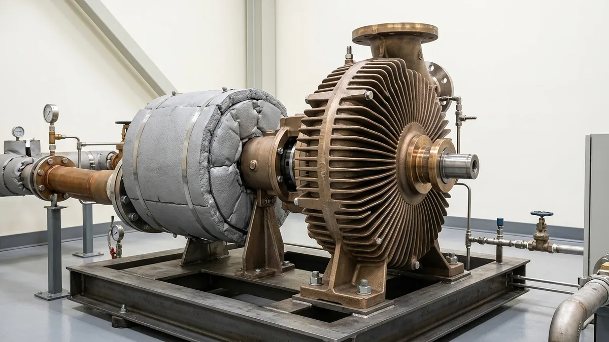
Hot Oil Pump Cavitation at 250°C–300°C: Thermodynamic NPSH Modeling, Vapor Pressure Physics & Field Mitigation Manual
A definitive high-temperature hydraulic cavitation manual, thermodynamic B-factor suppression standard, and Net Positive Suction Head (NPSH) engineering guide for process engineers, utility superintendents, and maintenance leads across Vatva GIDC, Narol, Odhav, Surat, and Gujarat.
Quick Answer
In the continuous textile processing mills, chemical synthesis plants, plywood pressing factories, and edible oil refining installations of Gujarat—spanning Ahmedabad (Vatva GIDC, Narol, Odhav), Surat, Ankleshwar, and Dahej—hot oil circulation pumps handle organic heat transfer fluids at operating temperatures between 250°C and 320°C. At these extreme thermal levels, cavitation dynamics differ fundamentally from cold ambient water applications. In fresh synthetic or mineral thermic fluids, low true vapor pressure (P_v < 0.05 bar) and high fluid thermodynamic suppression (the B-factor effect) should theoretically protect the pump from classic vapor cavitation. However, in real-world plant operations, thermal cracking of the fluid generates volatile light ends (C_1 - C_8) that spike effective vapor pressure beyond 1.2 bar. When combined with inadequate expansion tank elevation (Z_static < 3.0 meters), clogged suction strainers, or excessive suction pipe friction, available Net Positive Suction Head (NPSHa) plunges below required Net Positive Suction Head (NPSHr). The resulting high-temperature cavitation produces violent acoustic rattling (sounding like pumping gravel), severe impeller eye pitting, mechanical seal face heat checking, and up to 40% loss in delivered flow. Resolving high-temperature cavitation requires rigorous mathematical modeling of NPSHa, expansion tank re-elevation, deaeration boil-out, and precision hydraulic rebuilding in accordance with ISO 5199, ISO 2858, and DIN 24255 standards.
Key Takeaways
- Account for Volatile Light Ends in Vapor Pressure. Thermal fluid cracking raises effective P_v, causing cavitation even with positive expansion tank head.
- Maintain Minimum Expansion Tank Static Head (Z_static ≥ 3.5 m). Ensure expansion tank liquid level is located at least 3.5 to 5.0 meters above the pump centerline.
- Apply the Thermodynamic B-Factor Suppression Correction. Hydrocarbons exhibit milder cavitation damage than cold water due to localized evaporative cooling.
- Execute Thermal Degassing Boil-Out at 105°C-120°C. Vent low-boiling moisture and light fractions before ramping to 300°C.
Introduction
Across Gujarat's continuous process manufacturing plants—from the textile dyehouses and stenter drying ranges of Narol and Surat to the chemical intermediate reactor blocks of Vatva GIDC, Odhav, Ankleshwar, and Dahej—thermic fluid pumps circulate organic heat transfer media at bulk temperatures between 250°C and 320°C.
Unlike room-temperature water systems where vapor pressure is low and well-defined, high-temperature thermal loops present unique thermodynamic and chemical complexities:
- The True Vapor Pressure Myth: Fresh, un-degraded thermal fluids exhibit extremely low vapor pressures (P_v < 0.05 bar at 300°C). Based solely on fresh fluid datasheets, theoretical NPSHa appears abundant.
- The Thermal Cracking Reality: In operating plants, localized film overheating in boiler coils cracks hydrocarbon molecules into volatile light ends (C_1 - C_8). These light ends vaporize inside the pump impeller eye at suction pressures well above atmospheric pressure.
- The Mechanical Consequence: Vapor bubble collapse generates acoustic shock waves, eroding ductile iron impeller vanes, vibrating mechanical seals until brittle silicon carbide faces fracture, and causing catastrophic loss of heat delivery to stenters and reactors.
- The Engineering Standard: Following ISO 5199, ISO 2858, and DIN 24255 standards—calculating high-temperature NPSHa, applying thermodynamic B-factor corrections, elevating expansion tanks, and installing cavitation-resistant SS316 impellers—ensures stable hydraulic performance and long equipment life.
2. Master High-Temperature Cavitation & Hydraulic Threshold Matrix
Review the operational parameters, diagnostic symptoms, and required engineering thresholds for high-temperature pump cavitation:
| Hydraulic Condition | Fluid Temperature Range | Key Diagnostic Symptom | Root Cause Mechanism | Mandatory Engineering Correction |
|---|---|---|---|---|
| Fresh Fluid (P_v < 0.05 bar) | 280°C - 320°C | Smooth operation (< 1.8 mm/s) | Adequate NPSHa > NPSHr + 1.0 m | Maintain Z_static ≥ 3.5 m expansion head |
| Light-Ends Contamination | 250°C - 300°C | Gravel rattling; pressure wobble | Thermal cracking light-ends P_v > 1.0 bar | Thermal degassing boil-out at 115°C |
| Cold Moisture Flashing | 105°C - 120°C | Violent hammering; seal spray | 0.1% water flashes into 1700× steam | Hold degassing plateau; vent expansion tank |
| Suction Strainer Choking | Hot (> 200°C) | Suction vacuum; flow collapse | Carbon sludge choked in 40-mesh basket | Clean Y-strainer; convert to coarse mesh |
| Low-Flow Recirculation | Any Temperature | High axial 1X/2X vibration | Flow < 20% BEP causing eye recirculation | Open minimum continuous stable flow bypass |
3. The Thermal Physics, High-Temperature NPSH Math & Calculations
High-Temperature Available NPSH Equation (NPSHa = [P_exp - P_v] / [ρ· g] + Z - h_f)
In a closed thermic fluid loop, Net Positive Suction Head Available (NPSHa) at the pump suction nozzle centerline is calculated as:
Interactive Net Positive Suction Head (NPSHa) Sizer
Live ISO 5199 / API 610 Dynamic EngineWhere:
- P_expansion is absolute pressure in the expansion tank (101.3 kPa for atmospheric, or up to 150 kPa with nitrogen blanket).
- P_vapor is the effective fluid vapor pressure at operating temperature (300°C).
- ρ_fluid is hot oil density (≈ 680 - 720 kg/m³ at 300°C, compared to 870 kg/m³ cold).
- Z_expansion is the static liquid height from the pump centerline up to the expansion tank oil level (+4.0 m).
- h_suction friction is frictional head loss in suction piping, valves, and strainers.
Thermodynamic Suppression B-Factor & ΔNPSH_thermo Math
When a hydrocarbon fluid vaporizes in the pump suction eye, it absorbs latent heat of vaporization (ΔH_vap), locally cooling the surrounding liquid boundary layer. This localized cooling drops the effective local vapor pressure, suppressing bubble growth per the Hydraulic Institute B-factor equation:
- Because synthetic and mineral heat transfer oils have high boiling points, dense vapors, and moderate latent heat, high-temperature thermal oils exhibit a beneficial thermodynamic NPSH reduction (ΔNPSH_thermo ≈ 0.5 to 1.2 meters).
- However, this thermodynamic credit is completely overwhelmed if volatile light fractions contaminate the fluid.
Thermal Cracking Light-Ends Vapor Pressure Elevation (P_vapor Spike)
When thermal fluid cracks, the closed-cup flash point drops from 220°C to < 170°C, and vapor pressure (P_vapor) at 300°C spikes dramatically:
- Fresh Mineral Oil at 300°C: P_vapor ≈ 0.04 bar (4.0 kPa).
- Degraded Cracked Oil at 300°C: P_vapor ≈ 0.95 bar (95.0 kPa).
- With Z = 3.5 m and h_f = 1.8 m:
- If pump required NPSHr = 4.2 meters, the pump enters continuous, severe light-ends cavitation, causing flow collapse and acoustic rattling.
Suction Pipe Darcy-Weisbach Frictional Loss vs Temperature
Suction frictional loss (h_f) is determined by piping velocity (v) and Darcy friction factor (f):
- At 300°C, oil kinematic viscosity drops to ≈ 1.0 cSt, creating turbulent flow (Re > 200,000).
- Suction piping velocity must strictly be kept < 1.5 m/s to limit h_f < 0.5 meters and preserve suction head.
Cavitation Shock Wave Acoustic Energy & Impeller Material Pitting Rates
When microscopic vapor bubbles collapse against metal surfaces, microjets strike the surface at velocities > 1000 m/s, generating localized pressure pulses exceeding 10,000 bar:
- Nodular Ductile Iron (GGG 40.3): Moderate cavitation resistance; suffers surface spalling and vane thinning under sustained light-ends cavitation.
- SS316 / Duplex Stainless Steel: Exceptional work-hardening characteristics (> 2.5× cavitation erosion resistance compared to ductile iron).
4. The 5 Critical High-Temperature Cavitation Modes in Hot Oil Systems
Mode 1: Light-Ends Gaseous Cavitation from Thermal Cracking
- Mechanism: Low-boiling cracked hydrocarbon fractions boil in the pump eye at normal operating temperature.
- Symptoms: Erratic pressure gauge needle wobble (± 1.5 bar), gravel-rattling sound, flow drops by 25%.
- Fix: Conduct controlled deaeration boil-out at 115°C to vent volatile light ends via the expansion tank.
Mode 2: Low Static Head Vaporization Cavitation from Undersized Expansion Tanks
- Mechanism: Expansion tank located too low (Z < 2.0 meters above pump) or cold level set too low.
- Symptoms: Pump loses prime when operating above 260°C; cavitation worsens as boiler firing increases.
- Fix: Raise expansion tank support structure to achieve Z_static ≥ 4.0 meters and maintain 30% cold level.
Mode 3: Suction Strainer Carbon Mesh Vapor Binding
- Mechanism: Fine 40-mesh or 60-mesh wire screens in suction Y-strainers become blinded with baked carbon sludge.
- Symptoms: High suction vacuum reading (< -0.4 bar gauge); loud acoustic noise at pump suction nozzle.
- Fix: Remove fine mesh screens; install high-temperature 20-mesh or slotted basket strainers; clean regularly.
Mode 4: Low-Flow Internal Recirculation Cavitation (< 25% BEP)
- Mechanism: Process heating loops throttled back during low production, forcing pump below Minimum Continuous Stable Flow (MCSF).
- Symptoms: High axial 1X vibration, hydraulic surging, and casing temperature spike.
- Fix: Open dedicated three-way bypass control valve to maintain ≥ 20% BEP flow at all times.
Mode 5: Cold Startup Moisture Flashing Cavitation at 105°C
- Mechanism: Condensed atmospheric water in oil flashes into high-pressure steam at 100°C - 110°C.
- Symptoms: Violent mechanical shock waves, blown casing gaskets, shattered silicon carbide seal faces.
- Fix: Execute strict 4-hour thermal degassing hold at 105°C-115°C with open deaerator lines.
5. Step-by-Step Field Diagnostic & Cavitation Mitigation SOPs
Execute this structured engineering protocol when diagnosing and eliminating hot oil pump cavitation:
Phase 1: Suction Gauge Pressure & Acoustic FFT Spectrum Audit SOP
- Pressure Survey: Install calibrated high-temperature diaphragm pressure gauges on pump suction and discharge nozzles. Record suction gauge pressure at 50°C, 150°C, 250°C, and 300°C.
- Acoustic Spectrum Check: Measure high-frequency acoustic emission (ultrasonic peak > 20 kHz) and vibration velocity FFT. Confirm cavitation floor energy signature.
Phase 2: Laboratory Fluid Vapor Pressure & Distillation Test SOP
- Hot Sampling: Draw a 500 ml hot fluid sample using a closed-loop sample cooler.
- Lab Testing: Conduct ASTM D93 closed-cup flash point and ASTM D86 distillation curve testing. If light-ends fraction (< 200°C boiling point) exceeds 1.5%, fluid degassing is mandatory.
Phase 3: Expansion Tank Static Head & Deaerator Line Check SOP
- Height Verification: Measure vertical elevation (Z) from pump centerline to bottom of expansion tank (Z ≥ 3.5 m).
- Deaerator Piping Check: Confirm deaerator vent line from boiler outlet to expansion tank is unobstructed and warm.
Phase 4: Pump Suction Piping & Y-Strainer Optimization SOP
- Suction Line Sizing: Verify suction piping is at least one nominal pipe size larger than pump suction nozzle (v < 1.5 m/s).
- Strainer Cleaning: Isolate, drain, and clean the suction Y-strainer; replace fine mesh with heavy-gauge 20-mesh perforated basket.
Phase 5: Impeller Cavitation Pitting Repair & Lapping SOP
- Impeller Metrology: Extract back pull-out assembly; inspect impeller inlet vane tips for cavitation pitting or erosion channels.
- Hydraulic Reconditioning: Machine damaged vane inlet profiles, blend leading edges to OEM foil profile, or fit replacement SS316 impeller.
- Mechanical Seal Lapping: Lap monolithic silicon carbide seal faces on diamond table to < 2 light bands flatness.
Phase 6: Dynamic Rotor Balancing to ISO 5199 Grade G2.5 SOP
- Dual-Plane Balancing: Mount the repaired impeller, shaft, and keys onto an electronic dynamic balancing machine.
- Balance Certification: Achieve residual unbalance < 1.0 g\cdotmm/kg conforming to ISO 5199 Grade G2.5.
6. Materials of Construction, Metallurgy & Cavitation Resistance
Nodular Ductile Iron (GGG 40.3) & Cast Carbon Steel (ASTM A216 WCB)
- Pressure Containment: High-temperature Nodular Ductile Iron (EN-GJS-400-18-LT / GGG 40.3) or Cast Carbon Steel (ASTM A216 WCB) casings capable of withstanding thermal shock and 16 bar working pressure up to 350°C.
Monolithic Direct-Sintered Silicon Carbide (SSiC) Seal Faces
- Mechanical Seal Faces: Solid direct-sintered silicon carbide (SSiC) running against SSiC or Tungsten Carbide faces with flexible Grafoil or FFKM secondary O-rings.
Cavitation-Resistant SS316 & Duplex Stainless Steel Impellers
- Hydraulic Impellers: Precision investment cast SS316 or Duplex Stainless Steel impellers offering superior work-hardening, cavitation erosion resistance, and extended vane life at 320°C.
Pure Flexible Grafoil Gaskets & Secondary O-Rings
- Casing Joints: 100% pure exfoliated flexible graphite (Grafoil) die-formed rings and SS316 spiral-wound gaskets for leak-tight casing joints at 350°C.
7. The Utility Engineer's Cavitation Remediation Decision Matrix
Follow this structured engineering framework when determining corrective actions for cavitating pumps:
| Observed Cavitation Symptom | Confirmed Root Cause | Mandatory Corrective Engineering Action | Expected Turnaround Time |
|---|---|---|---|
| Loud rattling at 105°C-115°C | Moisture flash evaporation | Hold temp at 110°C; open deaerator vent valve | 2 to 4 hours on-site |
| Pressure fluctuation at 300°C | Thermal cracking light-ends | Execute 6-hour degassing boil-out + N2 blanketing | 12 to 24 hours on-site |
| High suction vacuum (< -0.3 bar) | Suction strainer clogged with carbon | Clean Y-strainer; upgrade to 20-mesh basket | 2 to 4 hours on-site |
| Impeller vane pitting / Flow drop > 20% | Severe sustained cavitation erosion | Workshop rebuild; install SS316 impeller + Balance | 2 to 3 working days |
8. Worked Gujarat Textile, Chemical & Processing Mill Case Studies
Case 1: Vatva GIDC Textile Dyehouse Hot Oil Pump Cavitation Overhaul
- Plant Context: A modern textile dyehouse in Vatva GIDC operating a 2.5 Million kcal/hr thermic fluid heater with a 150 m³/h circulation pump (295°C).
- Problem: The pump experienced chronic gravel-rattling cavitation whenever oil temperature passed 270°C; mechanical seal faces shattered twice in 45 days.
- Root Cause: Fluid lab tests revealed flash point had dropped from 225°C to 168°C due to severe thermal cracking. Light-ends vapor pressure (P_v = 1.15 bar) caused NPSHa to collapse to 1.8 meters (below pump required NPSHr = 3.8 meters).
- Action Plan: Teflow Pumps engineering team:
- Executed a controlled 8-hour thermal degassing boil-out at 115°C-130°C, venting light fractions. - Overhauled pump in our Ahmedabad workshop; replaced pitted cast iron impeller with precision investment cast SS316 impeller. - Lapped monolithic SSiC mechanical seal faces on diamond table. - Dynamically balanced impeller to ISO 5199 Grade G2.5 and installed nitrogen blanketing (0.3 bar) on expansion tank.
- Outcome: Zero cavitation at 295°C; delivered full rated 150 m³/h flow; mechanical seal ran leak-free for over 24 consecutive operating months.
Case 2: Narol Continuous Cotton Stenter Hot Oil Circulation Cavitation Fix
- Plant Context: A continuous cotton stenter drying facility in Narol operating dual 90 m³/h hot oil pumps (280°C).
- Problem: High suction vacuum and cavitation rattling caused by a clogged 60-mesh suction strainer.
- Action Plan: Removed fine wire mesh and replaced with heavy-duty 20-mesh perforated SS316 basket strainer.
- Outcome: Suction head increased by +2.2 meters; cavitation noise completely eliminated.
Case 3: Surat Synthetic Weaving Thermic Fluid Pump NPSH Recovery
- Plant Context: A polyester yarn processing plant in Surat operating dual thermic fluid pumps (270°C).
- Problem: Low expansion tank elevation (Z = 1.8 meters) caused pump to lose prime when running at full capacity.
- Action Plan: Re-elevated expansion tank support structure to Z = 4.5 meters above pump centerline.
- Outcome: Increased NPSHa by +3.8 meters; zero loss-of-prime incidents during peak production.
Case 4: Odhav Industrial Estate Plywood Press Circulation Audit
- Plant Context: A laminate pressing facility in Odhav operating hot oil platens at 230°C.
- Problem: Impeller vane cavitation pitting caused a 22% reduction in pump flow rate.
- Action Plan: Replaced damaged impeller with precision dynamically balanced SS316 impeller and optimized suction piping.
- Outcome: Full 4.5 bar differential pressure restored; platen heating time reduced by 24%.
Case 5: Ankleshwar GIDC Specialty Chemical Reactor Thermal Loop Recovery
- Plant Context: A chemical synthesis plant in Ankleshwar GIDC operating at 310°C.
- Problem: Severe low-flow cavitation during reactor holding cycles.
- Action Plan: Installed an automatic minimum continuous stable flow bypass valve set at 25% BEP.
- Outcome: Casing temperature stabilized; vibration reduced from 5.2 mm/s to 1.10 mm/s RMS.
Case 6: Dahej PCPIR Petrochemical Terminal Heat Transfer Circulation Audit
- Plant Context: A chemical storage terminal in Dahej PCPIR operating high-flow BB1 split-case hot oil pumps (2200 m³/h).
- Problem: Cavitation rattling during winter heavy oil tanker unloading operations.
- Action Plan: Verified thermodynamic B-factor suppression and optimized suction manifold isolation valves.
- Outcome: Restored smooth, cavitation-free pumping across full operating capacity.
9. Comprehensive Master Hot Oil Pump NPSH & Cavitation Checklist
Execute this hydraulic verification protocol to eliminate pump cavitation and ensure continuous reliability:
Hot Oil Pump Cavitation Elimination & NPSH Verification Protocol
10. Summary & Specialized High-Temperature Pump Services in Gujarat & India
Eliminating hot oil pump cavitation at 250°C-300°C—modeling high-temperature NPSHa, applying thermodynamic B-factor suppression, purging volatile light ends through thermal degassing boil-out, elevating expansion tanks, fitting cavitation-resistant SS316 impellers, and dynamically balancing rotating assemblies to ISO 5199 Grade G2.5 across Vatva GIDC, Narol, Odhav, Surat, Ankleshwar, and Dahej—conforming to ISO 5199, ISO 2858, and DIN 24255 standards—is the proven engineering standard for industrial reliability.
Partnering directly with an established Gujarat rotating machinery manufacturer provides textile mill managers, utility superintendents, and process engineers with immediate technical access to specialized hydraulic diagnostic teams, acoustic FFT analyzers, precision dynamic balancing facilities, custom SS316 impeller casting, and genuine spares dispatched directly from our Ahmedabad factory. Our technical engineers provide emergency on-site troubleshooting, turnkey pump overhauls, and complete thermal loop audits.
Teflow Pumps operates a specialized industrial machinery manufacturing and service facility in Ahmedabad, providing emergency thermic fluid pump overhauls, high-temperature mechanical seal replacements, precision dynamic balancing, laser alignment, custom impeller casting, and genuine rotating equipment spares across Gujarat and India conforming to ISO 5199, ISO 2858, DIN 24255, and IS 5120 standards.
- Direct Technical & Emergency Helpline: +91 98251 62709
- WhatsApp Technical Desk: Share suction gauge pressures, operating oil temperatures (°C), expansion tank heights (Z), fluid lab reports (flash point), pump nameplate photos, or audio recordings of pump noise to wa.me/919825162709 for immediate technical review, NPSH calculation, and formal quotation.
- Request an On-Site Hot Oil Pump Cavitation & Hydraulic Audit: Contact our senior rotating equipment engineers for emergency plant surveys, hot alignment proposals, and formal quotation. Our engineering team conducts comprehensive thermal evaluations, verifies ISO 5199 criteria, provides precision on-site or workshop reconditioning, and dynamically balances overhauled hot oil pumps to ensure maximum uptime across Gujarat's textile and chemical processing mills. We provide rapid technical evaluations, on-site plant surveys, and formal quotes.