
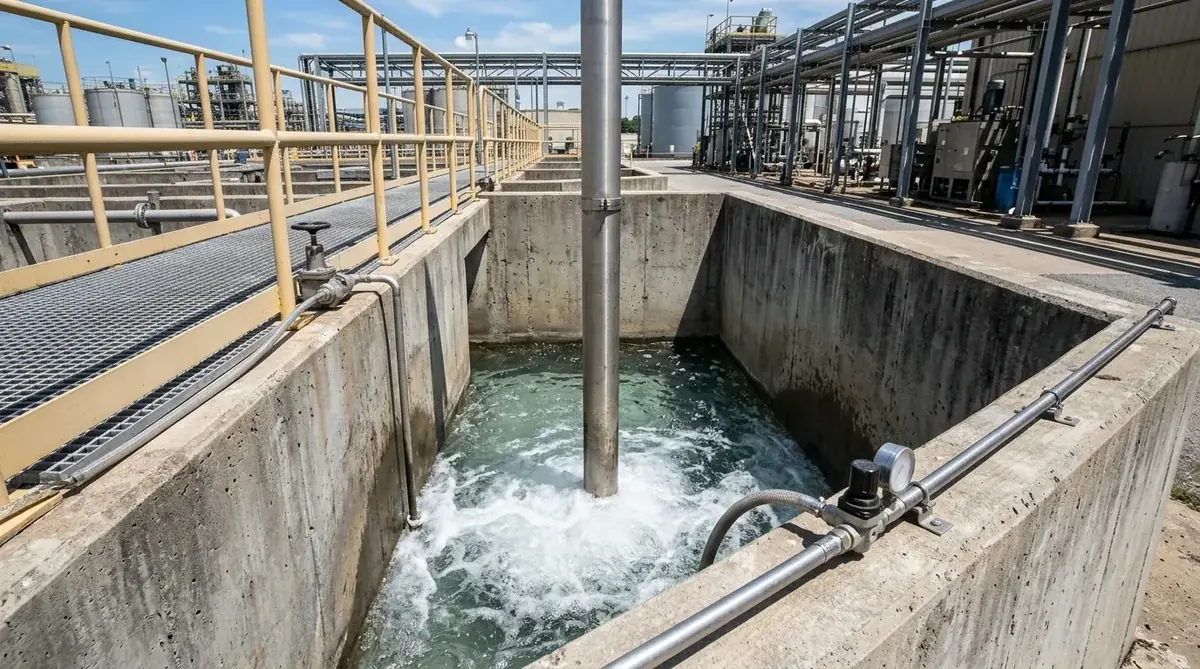
Air Lift Pump Calculator: Sizing Airflow, Submersion Ratios & ETP Sump Slurry Hydraulics Manual
A definitive two-phase gas-liquid hydraulic standard, Lorenz airlift mathematical derivation manual, and effluent treatment sump airlift design guide for plant maintenance engineers, ETP superintendents, and environmental utility leads across Vatva GIDC, Narol, Odhav, Surat, and Gujarat.
Quick Answer
In the effluent treatment plants (ETP), central effluent treatment plants (CETP), chemical equalization tanks, and neutralization sumps of Gujarat—spanning Ahmedabad (Vatva GIDC, Narol, Odhav), Surat, Ankleshwar, and Dahej—pumping heavy chemical sludge, abrasive grit, and corrosive wastewater rapidly destroys mechanical pump impellers and mechanical seals. The air lift pump provides a sealless, valveless, zero-moving-part pneumatic alternative that uses compressed air injection to lift slurries via two-phase buoyant density reduction. Calculating the required free air volume (V_air) depends on liquid discharge rate (Q_liquid), lift height above water level (H_lift), submergence depth (H_sub), and compressor injection pressure (P_air). Sizing follows the Lorenz and Nicklin two-phase lift equation: V_air (m³/min) = [Q_liquid (m³/min) · H_lift] / [C · \ln(1 + (H_sub) / (10.33))], where the submersion ratio must be maintained at R_sub = (H_sub) / (H_sub + H_lift) ≥ 0.60 conforming to ISO 5199, ISO 2858, and Hydraulic Institute (HI 14.6) standards.
Key Takeaways
- Master the Lorenz Air Lift Equation. Calculate required compressor airflow using V_air = [Q_l · H_l] / [C · \ln(1 + H_s / 10.33)].
- Maintain Optimal Submersion Ratios. Ensure R_sub = (H_sub) / (H_total) ≥ 0.60 to achieve 40%-50% hydraulic efficiency.
- Size Air Injection Operating Pressure. Calculate air pressure P_air (bar) = [ρ· g · H_sub] / [10^5] + 0.50 bar to overcome static head.
- Select Heavy-Duty Chemical Metallurgy. Fabricate eductor pipes from solid polypropylene, PVDF, or PTFE-lined carbon steel to resist corrosive acids.
Introduction
Across Gujarat's industrial chemical corridors—including the high-TDS effluent equalization pits of Vatva GIDC and Odhav, the large-scale textile wastewater treatment facilities of Narol and Surat, the pharmaceutical intermediate neutralization sumps of Ankleshwar, and the petrochemical drainage pits of Dahej—transferring abrasive slurry, toxic acid waste, and heavy grit presents continuous maintenance challenges.
Conventional mechanical centrifugal and submersible pumps suffer rapid seal failure, bearing seizure, and impeller erosion when handling thick sludge with suspended solids:
- The Airlift Advantage: The air lift pump operates without an impeller, shaft, mechanical seal, or internal submerged bearings.
- The Operating Principle: Compressed air is injected at the bottom of a submerged vertical riser pipe (eductor). The injected air bubbles reduce the bulk density of the fluid column inside the pipe (ρ_mixture < ρ_liquid). The surrounding dense liquid in the sump exerts hydrostatic pressure that forces the aerated two-phase mixture upward to the discharge point.
- The Engineering Challenge: Airlift pumps require exact mathematical balancing of submergence depth, pipe diameter, and compressed air volumetric flow rate. Improper sizing results in gas slip, flow surging, or complete lift stalling.
- The Engineering Standard: Following ISO 5199, ISO 2858, and Hydraulic Institute (HI 14.6) standards—mastering Lorenz two-phase derivations, sizing compressor delivery pressure, and engineering non-clogging footpiece nozzles—guarantees continuous, maintenance-free ETP sump operation.
2. Master Airlift vs Mechanical Submersible Pump Comparison Matrix
Review the engineering parameters, maintenance profiles, and practical operating boundaries for airlift systems versus mechanical submersible pumps:
| Performance Metric | Industrial Air Lift Pump System | Submersible Slurry Centrifugal Pump | Engineering Advantage of Airlift |
|---|---|---|---|
| Moving Parts in Sump | Zero (Completely sealless & valveless) | Rotating impeller, shaft, mechanical seal | Zero mechanical wear or abrasion seizure |
| Solids Handling Limit | Any solid that passes pipe diameter (D_pipe) | Limited by impeller vane passage (< 25 mm) | Immune to stringy rags, plastic film & grit |
| Corrosion Resistance | Solid Polypropylene / PVDF / PTFE Lined | Limited by motor casing & seal face metallurgy | 100% inert to concentrated acid slurries |
| Typical Efficiency (η) | 35% - 55% (Thermodynamic two-phase) | 50% - 75% (Mechanical shaft) | Higher overall reliability despite lower η |
| Minimum Submergence (R_sub) | R_sub ≥ 0.50 - 0.70 required | Can pump down to pump volute level | Requires deep sump or drilled casing well |
| Maintenance Interval | > 36 - 60 months (Clean air nozzle) | 3 - 6 months (Seal/bearing overhaul) | 10× lower plant maintenance labor |
3. The Fluid Dynamics Physics & Two-Phase Lift Mathematical Derivations
The Fundamental Lorenz Air Lift Equation (V_air = [Q_l H_l] / [C \ln(1 + H_s / 10.33)])
The required volumetric free air delivery (V_air at standard atmospheric conditions) to lift a given volumetric flow rate of liquid (Q_liquid) is governed by the Lorenz thermodynamic equation:
Interactive Sump Air Lift & Compressor Sizer
Live ISO 5199 / API 610 Dynamic EngineWhere:
- V_air is the free air volume at atmospheric pressure in m³/min (or CFM / 35.315).
- Q_liquid is the required liquid discharge rate in m³/min (Q_m³/h / 60).
- H_lift is the static lift height from the sump water level to the discharge pipe outlet in meters.
- H_sub is the submergence depth of the air injection footpiece below the water level in meters.
- C is the empirical lift constant (C = 200 - 245 for well-designed industrial airlift footpieces; C = 160 - 180 for small-diameter un-aerated tubes).
- Sizing Calculation Example: An ETP sump in Vatva GIDC requires pumping Q_liquid = 30 m³/h (0.50 m³/min) of chemical effluent with H_lift = 3.0 meters, H_sub = 6.0 meters, and C = 220:
Submersion Ratio Mathematics (R_sub = (H_sub) / (H_sub + H_lift))
The Submersion Ratio (R_sub or Submergence Percentage) is the primary determinant of hydraulic efficiency:
- Optimal Operating Range: R_sub = 0.60 to 0.75 (Efficiency η = 45% - 55%).
- Minimum Allowable Limit: R_sub = 0.50 (Efficiency η ≈ 30% - 35%).
- Stalling Boundary: If R_sub < 0.40, buoyant energy is insufficient to overcome pipe friction; airflow slips through liquid without lifting fluid.
Two-Phase Gas-Liquid Density & Hydrostatic Buoyancy Math (ρ_mix = [ρ_l Q_l + ρ_g Q_g] / [Q_l + Q_g])
Hydrostatic equilibrium between the outside liquid column and internal aerated column establishes upward flow:
Compressor Sizing & Air Injection Pressure Derivations (P_inj = ρg H_s + ΔP_nozzle)
The air compressor must deliver air at sufficient gauge pressure to overcome the static hydrostatic water head at the footpiece plus nozzle pressure drop:
- Calculation: For H_sub = 6.0 m of effluent (ρ= 1050 kg/m³):
Two-Phase Flow Regimes (Bubbly, Slug, Churn, Annular) & Slip Velocity Math
- Bubbly Flow (Low Airflow): Small discrete bubbles rise through liquid. High gas slip velocity; low liquid lifting capacity.
- Slug Flow (Optimal Industrial Airlift): Large bullet-shaped Taylor bubbles occupy almost the full pipe cross-section, pushing solid liquid slugs upward with maximum efficiency.
- Churn / Annular Flow (Excessive Airflow): Turbulent chaotic gas core with liquid film along pipe wall; excessive air waste.
Footpiece Injector Geometries (Annular Ring, Perforated Diffuser, Radial Jet)
- Annular Ring Sleeve: Air enters through a circumferential annular gap surrounding the eductor pipe wall, creating uniform bubble distribution with zero internal flow obstruction.
- Perforated Diffuser: Multiple 2.0 - 4.0 mm holes drilled into a submerged jacket, generating fine-to-medium bubbles for low-viscosity slurries.
- Radial Jet Nozzle: High-velocity air jets focused centrally to agitate and break up settling sludge blankets at the suction inlet.
4. The 6 Critical Causes of Airlift Flow Failure & Sump Surging
Cause 1: Insufficient Sump Submergence Depth (R_sub < 0.45)
- Mechanism: Sump liquid level drops during dry batch cycles, lowering H_sub and reducing submergence ratio below 0.45.
- Impact: Hydrostatic driving head collapses; pump stops lifting liquid while compressed air vents freely.
- Fix: Install level controller to throttle airflow or deepen footpiece into a suction sump boot.
Cause 2: Air Compressor Pressure Starvation & Flow Choking
- Mechanism: Sizing an air blower with insufficient delivery pressure to overcome starting static water column.
- Impact: Water backs into the air supply line; air bubbles cannot discharge into the footpiece.
- Fix: Size compressor pressure for 1.5× hydrostatic submergence head (P_air ≥ [ρg H_s] / [10^5] + 0.5 bar).
Cause 3: Injector Nozzle Salt Encrustation & Heavy Sludge Scaling
- Mechanism: Calcium carbonate or iron hydroxide precipitates inside small air injection orifices.
- Impact: Air injection holes clog, choking airflow and inducing violent slugging.
- Fix: Install self-cleaning elastomeric sleeve injectors or clean footpiece with acid flushing.
Cause 4: Oversized Eductor Pipe Diameter Inducing Gas Slip
- Mechanism: Selecting an oversized riser pipe (D_pipe > 150 mm) for low liquid flow rates.
- Impact: Air bubbles rise freely up the center of the pipe without lifting the liquid wall (gas bypass slip).
- Fix: Size pipe diameter to maintain two-phase superficial velocity v_two-phase = 2.5 - 4.5 m/s.
Cause 5: Dense Silt & Heavy Grit Slumping at Suction Foot
- Mechanism: Heavy settling of sand, grit, or pigment sludge blocks the suction inlet bell-mouth.
- Impact: Liquid cannot enter the riser; air blows backward through the sump.
- Fix: Install auxiliary air-scouring bottom jet nozzle to fluidize settled solids before starting lift.
Cause 6: Air Supply Line Pressure Drops & Regulator Throttling
- Mechanism: Long, undersized pneumatic lines from central compressor plant creating excessive air pressure drop.
- Impact: Air pressure at the footpiece fluctuates, causing erratic flow pulsing.
- Fix: Install a local air receiver tank (200 - 500 liters) adjacent to the ETP sump.
5. Step-by-Step Field Airlift Sizing, Diagnostic & Commissioning SOPs
Execute this structured engineering protocol when sizing, commissioning, or troubleshooting ETP sump airlift systems:
Phase 1: Sump Depth, Submergence (H_s) & Static Lift (H_l) Survey SOP
- Dimensional Logging: Measure minimum liquid level (H_sub) and total lift height to discharge point (H_lift).
- Submersion Ratio Verification: Calculate R_sub = (H_sub) / (H_sub + H_lift); verify R_sub ≥ 0.60.
Phase 2: Slurry Specific Gravity (SG) & Solids Volume Logging SOP
- Density Measurement: Measure slurry specific gravity using a hydrometer or pycnometer.
- Settling Rate Audit: Measure volumetric solids concentration in an Imhoff cone to determine agitation requirements.
Phase 3: Eductor Pipe Diameter (D_pipe) & Superficial Velocity SOP
- Diameter Sizing: Size riser pipe diameter (D_inner) using:
- Target Velocity: Ensure target two-phase mixture velocity is maintained at 3.0 - 4.0 m/s.
Phase 4: Air Compressor Delivery Flow (FAD) & Pressure Sizing SOP
- Free Air Volume: Compute V_air via Lorenz formula; add 20% design margin for compressor sizing.
- Pressure Setting: Set compressor regulator to P_gauge = [SG × 9.81 × H_sub] / [10] + 0.40 bar.
Phase 5: Dynamic Balancing to ISO 5199 Grade G2.5 for Associated Rotary Equipment SOP
- Compressor & Blower Balancing: Dynamically balance rotary lobe blowers or compressor impellers.
- Balance Certification: Achieve residual unbalance < 1.0 g\cdotmm/kg conforming to ISO 5199 Grade G2.5.
Phase 6: Pneumatic Commissioning, Bubble Uniformity & Flow Audit SOP
- Initial Injection: Slowly open air supply valve; observe bubble pattern and establish steady Taylor slug flow.
- Flow Rate Verification: Measure liquid discharge flow rate at outfall weir; confirm steady flow without surging.
6. Materials of Construction, Metallurgy & Footpiece Linings
Solid Polypropylene & PVDF Thermoplastic Eductor Pipes
- Acid Slurry Resistance: Solid extruded Polypropylene (PP) and PVDF riser pipes provide 100% chemical inertness to hydrochloric acid, sulfuric acid, and bleach slurries up to 95°C.
PTFE / PFA Lined Carbon Steel Columns for Severe Acids
- Structural Strength: Heavy-wall carbon steel pipes lined with 3.5 - 5.0 mm virgin PTFE/PFA provide high structural stiffness for deep sumps (> 6 meters) combined with total chemical resistance.
SS316 & Duplex SS (2205) Footpiece Assemblies
- Mechanical Durability: Precision CNC-machined SS316 and Duplex SS 2205 air injection collars with circumferential annular distribution rings.
Monolithic Direct-Sintered Silicon Carbide (SSiC) Jet Nozzles
- Grit Erosion Immunity: Monolithic direct-sintered SSiC air nozzles provide extreme hardness (> 2500 HV) that prevents hole enlargement when pumping abrasive quartz and silica sand slurries.
7. The ETP Engineer's Airlift Sizing Decision Matrix
Follow this structured engineering guide when selecting and sizing airlift pumping systems for wastewater sumps:
| Sump Depth & Submergence (H_sub) | Lift Height (H_lift) | Submersion Ratio (R_sub) | Airflow Requirement (V_air / Q_liquid) | Recommended System Configuration |
|---|---|---|---|---|
| 6.0 - 8.0 meters (Deep Sump) | 2.0 - 3.0 meters | 0.67 - 0.75 (High) | 1.5 - 2.5 m³ air / m³ liquid | High efficiency; rotary screw compressor (1.5 bar) |
| 4.0 - 5.0 meters (Standard) | 2.0 - 2.5 meters | 0.60 - 0.67 (Optimal) | 2.5 - 4.0 m³ air / m³ liquid | Standard airlift; Roots rotary lobe blower (1.0 bar) |
| 2.5 - 3.5 meters (Shallow Sump) | 2.0 - 3.0 meters | 0.50 - 0.55 (Marginal) | 5.0 - 8.0 m³ air / m³ liquid | Requires bottom air jetting; higher air consumption |
| < 2.0 meters (Very Shallow) | > 3.0 meters | < 0.40 (Unstable) | > 12 m³ air / m³ liquid | Airlift unviable; install progressive cavity or cantilever pump |
8. Worked Gujarat Chemical ETP, Textile CETP & Industrial Case Studies
Case 1: Vatva GIDC Chemical Wastewater Equalization Sump Airlift Fix
- Plant Context: A specialty dye intermediate plant in Vatva GIDC operating a deep (7.5 m) neutralization pit containing 35% acidic slurry with heavy iron sludge precipitates.
- Problem: Submersible cantilever pumps failed every 6 to 8 weeks due to seal erosion and motor casing corrosion, costing over 6 lakh INR annually in repairs.
- Root Cause: Abrasive iron hydroxide crystals destroyed mechanical seals and ground down cast iron impellers.
- Action Plan: Teflow Pumps engineering team:
- Designed and installed an all-PVDF air lift pump column with a 100 mm eductor bore. - Submergence was set to H_sub = 5.2 m with H_lift = 2.3 m (R_sub = 0.69). - Configured a dedicated rotary screw compressor delivering 1.4 m³/min at 1.2 bar. - Dynamically balanced the compressor motor drive to ISO 5199 Grade G2.5.
- Outcome: Achieved continuous 25 m³/h sludge transfer with zero submerged moving parts; operating continuously for over 28 months with zero maintenance downtime.
Case 2: Narol Continuous Textile CETP Sludge Lift Airflow Sizing
- Plant Context: A continuous textile processing CETP in Narol pumping fibrous lint and dye slurry from primary clarifier sumps.
- Problem: Centrifugal pumps suffered continuous impeller clogging from cotton lint and fabric threads.
- Action Plan: Installed a sealless air lift pump system with annular air injection sleeve.
- Outcome: Completely eliminated rag and fiber clogging; reduced manual cleaning labor from daily to zero.
Case 3: Odhav Effluent Treatment Plant Grit Sump Airlift Overhaul
- Plant Context: An industrial CETP in Odhav pumping heavy abrasive silica grit from the grit chamber sump.
- Problem: High air consumption and intermittent flow stalling due to severe nozzle scale clogging.
- Action Plan: Replaced clogged drilled nozzles with a monolithic SSiC ceramic annular footpiece.
- Outcome: Air consumption dropped by 38%; achieved continuous, steady grit evacuation.
Case 4: Surat Synthetic Dye Waste Acid Sump Airlift Remediation
- Plant Context: A synthetic dye manufacturer in Surat transferring hot waste acid (65°C, pH 1.2) containing dye solids.
- Problem: High fluid temperature caused thermal cavitation in conventional pumps.
- Action Plan: Engineered a solid Polypropylene airlift column with bottom air-scouring jets.
- Outcome: Unaffected by thermal cavitation; transferred hot acid waste reliably without chemical attack.
Case 5: Ankleshwar GIDC Pharma Equalization Neutralization Airlift Setup
- Plant Context: A pharmaceutical bulk drug manufacturing plant in Ankleshwar GIDC transferring solvent-contaminated wastewater.
- Problem: Electric submersible pump motors presented an explosion risk in a Zone 1 hazardous area.
- Action Plan: Installed an intrinsically safe pneumatic air lift pump powered by plant instrument air.
- Outcome: Achieved 100% ATEX/flameproof safety compliance with zero electrical hardware in the sump.
Case 6: Dahej PCPIR Petrochemical Effluent Pit Airlift Modernization
- Plant Context: A petrochemical complex in Dahej PCPIR transferring caustic brine sludge from drainage sumps.
- Problem: Extreme caustic corrosion (48% NaOH) caused rapid failure of stainless steel pump casings.
- Action Plan: Installed a PTFE-lined carbon steel air lift pump with Duplex SS 2205 air distribution manifold.
- Outcome: Extended maintenance lifecycle from 3 months to over 48 months of continuous service.
9. Comprehensive Master Airlift Sizing & Commissioning Checklist
Execute this hydraulic calculation and pneumatic commissioning protocol before operating ETP sump airlift systems:
Air Lift Pump Sizing & Pneumatic Commissioning Protocol
10. Summary & Specialized ETP Pumping Services in Gujarat & India
Sizing and operating sealless air lift pump systems—mastering Lorenz two-phase gas-liquid fluid dynamics, calculating compressor injection pressure and airflow volume, maintaining optimal submersion ratios (R_sub ≥ 0.60), selecting chemical-inert fluoropolymer and thermoplastic riser pipes, and dynamically balancing rotary compressor equipment to ISO 5199 Grade G2.5 across Vatva GIDC, Narol, Odhav, Surat, Ankleshwar, and Dahej—conforming to ISO 5199, ISO 2858, and DIN 24255 standards—is the proven engineering standard for industrial ETP and CETP wastewater management.
Partnering directly with an established Gujarat rotating and pneumatic machinery manufacturer provides chemical plant maintenance engineers, ETP superintendents, and environmental utility leads with immediate technical access to on-site wastewater hydraulic audit teams, ultrasonic flow meters, pressure logging instrumentation, custom thermoplastic machining workshops, dynamic balancing facilities, and genuine spares dispatched directly from our Ahmedabad factory. Our technical engineers provide emergency on-site troubleshooting, turnkey airlift retrofits, and complete wastewater sump optimizations.
Teflow Pumps operates a specialized industrial machinery manufacturing and service facility in Ahmedabad, providing emergency pump overhauls, custom air lift pump column fabrication, PFA/PTFE lined component manufacturing, dynamic balancing, laser alignment, and genuine rotating equipment spares across Gujarat and India conforming to ISO 5199, ISO 2858, DIN 24255, and IS 5120 standards.
- Direct Technical & Emergency Helpline: +91 98251 62709
- WhatsApp Technical Desk: Share sump depth dimensions (H_sub, H_lift), slurry flow requirements (Q_m³/h), wastewater chemistry, photos of existing sumps, or flow stalling symptoms to wa.me/919825162709 for immediate technical review, airflow calculation, and formal quotation.
- Request an On-Site ETP Sump Survey & Airlift Sizing Proposal: Contact our senior rotating equipment engineers for emergency plant surveys, airlift design proposals, and formal quotation. Our engineering team conducts comprehensive thermal evaluations, verifies ISO 5199 criteria, provides precision on-site or workshop reconditioning, and dynamically balances overhauled hot oil pumps to ensure maximum uptime across Gujarat's textile and chemical processing mills. We provide rapid technical evaluations, on-site plant surveys, and formal quotes.