
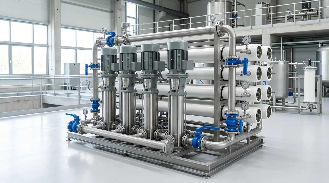
Water Pump Flow Rate Calculator for RO & Booster Sets: Sizing Math, Pressure Physics & Overhaul Guide
A definitive industrial water hydraulics standard, reverse osmosis feed sizing manual, and high-pressure multi-stage booster pump maintenance guide for water treatment superintendents, maintenance engineers, and utility leads across Vatva GIDC, Narol, Odhav, Surat, and Gujarat.
Quick Answer
In the industrial water treatment facilities, common effluent treatment plants (CETP), textile zero-liquid discharge (ZLD) units, and pharmaceutical purified water systems of Gujarat—spanning Ahmedabad (Vatva GIDC, Narol, Odhav), Surat, Ankleshwar, and Dahej—accurate calculation of water pump flow rates and booster pressures is critical to plant throughput. Sizing high-pressure reverse osmosis (RO) feed pumps requires integrating membrane separation thermodynamics with centrifugal fluid dynamics. The required raw water feed flow rate (Q_feed) is derived from target permeate production (Q_permeate) divided by system recovery ratio (Y_recovery): Q_feed (m³/h) = [Q_permeate (m³/h)] / [Y_recovery], while reject concentrate flow equals Q_reject = Q_feed - Q_permeate. In addition, total dynamic booster head (H_booster) must overcome osmotic backpressure, membrane net driving pressure, and internal friction losses: H_total (meters) = [(ΔP_osmotic + ΔP_net + ΔP_piping) × 10.197] / [Specific Gravity]. Sizing, testing, and overhauling multi-stage booster pumps conforms to ISO 5199, ISO 2858, and DIN 24255 standards.
Key Takeaways
- Master the RO Feed Recovery Equation. Calculate total booster suction feed flow using Q_feed = (Q_permeate) / (Y_recovery) based on system design recovery.
- Compute Pipe Hydraulic Flow Velocity. Size suction and discharge headers using Q = [π· D²] / [4] · v · 3600 to maintain velocities below 1.5 m/s on suction.
- Calculate High-Pressure Booster Head. Size multi-stage pump total dynamic head to overcome feed water osmotic pressure (≈ 0.08 bar per 1000 ppm TDS).
- Diagnose Inter-Stage Internal Wear. Radial clearance expansion across multi-stage wear bushings causes booster pressure collapse and severe energy waste.
Introduction
Across Gujarat's water-intensive manufacturing corridors—including the high-TDS chemical wastewater zones of Vatva GIDC and Ankleshwar, the massive textile CETPs of Narol and Surat, and the seawater desalination facilities of Dahej—industrial water treatment systems depend on continuous high-pressure booster pumping.
Reverse osmosis (RO) membranes require high feed pressures (14 to 70 bar) to overcome natural osmotic pressure and force purified water through microscopic polyamide membrane pores:
- The Sizing Challenge: An undersized booster pump fails to deliver required permeate capacity (Q_permeate), while an oversized pump causes excessive energy consumption, membrane compaction, and frequent pressure relief valve blowing.
- The Feed Flow Equation: Raw feed water flow (Q_feed) must always be sized larger than permeate output to accommodate reject concentrate flushes (Q_reject) that sweep away concentrated salts.
- The Multi-Stage Wear Phenomenon: Multi-stage centrifugal booster pumps utilize stacked impellers and diffusers. When inter-stage throttle bushings wear due to abrasive suspended silt or mineral scaling, high-pressure water recirculates internally, causing booster discharge pressure to collapse.
- The Engineering Standard: Following ISO 5199, ISO 2858, and DIN 24255 standards—mastering mass balance equations, verifying suction NPSHa, machining Duplex SS components, and dynamically balancing vertical multi-stage pump shafts—guarantees stable water treatment operations.
2. Master RO & Booster Pump Hydraulics Sizing Matrix
Review the engineering parameters, flow math, and pressure requirements across major industrial water treatment and booster applications:
| Application Sector | Typical Feed TDS (ppm) | Design Recovery (Y) | Target Permeate (Q_p) | Required Feed Flow (Q_feed) | Booster Pressure Range | Recommended Metallurgy |
|---|---|---|---|---|---|---|
| Textile CETP / ZLD Loop | 4,000 - 8,000 ppm | 70% - 75% | 50 m³/h | 66.7 - 71.4 m³/h | 16 - 25 bar | Duplex SS 2205 / SS316 |
| Pharma Purified Water (PW) | < 500 ppm | 75% - 80% | 15 m³/h | 18.8 - 20.0 m³/h | 10 - 16 bar | Electro-Polished SS316L |
| Chemical ETP Effluent RO | 8,000 - 15,000 ppm | 60% - 65% | 30 m³/h | 46.2 - 50.0 m³/h | 25 - 40 bar | Super Duplex SS 2507 |
| Seawater Desalination (SWRO) | 35,000 - 45,000 ppm | 40% - 45% | 100 m³/h | 222.2 - 250.0 m³/h | 55 - 70 bar | Super Duplex SS 2507 |
| Building Pressure Booster | < 300 ppm | 100% (Direct) | 40 m³/h | 40.0 m³/h | 4 - 8 bar | SS304 / SS316 Inline |
3. The Fluid Dynamics Physics & Water Flow Mathematical Derivations
RO Permeate Recovery & Mass Balance Math (Q_feed = (Q_p) / (Y))
In any membrane separation process, total feed water flow (Q_feed) splits into two streams: purified permeate (Q_permeate) and concentrated reject brine (Q_reject):
Interactive Engineering Hydraulic Sizer
Live ISO 5199 / API 610 Dynamic EngineThe system recovery ratio (Y_recovery) is the fraction of feed converted to permeate:
The concentrate reject flow rate (Q_reject) required to prevent membrane fouling is:
- Sizing Calculation: An industrial RO system in Narol requires Q_permeate = 60 m³/h at a design recovery of 75% (Y = 0.75):
Pipe Velocity Flow Rate Sizing Formula (Q = A · v · 3600)
To calculate water flow rate from pipe internal diameter (D_meters) and fluid flow velocity (v_m/s):
- Sizing Guidelines: To prevent suction cavitation (NPSHa deficit) and minimize piping friction loss:
- Suction line velocity: Maintain v_suction ≤ 1.2 - 1.5 m/s. - Discharge line velocity: Maintain v_discharge ≤ 2.0 - 2.5 m/s.
Multi-Stage High-Pressure Booster Head Math (H_total = [ΔP · 10.197] / [SG])
The total dynamic head required by the RO high-pressure booster pump (H_booster) must overcome:
- Feed osmotic backpressure (ΔP_osmotic).
- Net driving pressure across membrane pores (ΔP_net).
- Membrane vessel and piping friction losses (ΔP_friction).
- Permeate backpressure (P_permeate).
Converting pressure from bar into total dynamic head (H_meters):
Osmotic Pressure Calculations Based on Feed Water TDS
Osmotic pressure (\Pi) increases proportionally with total dissolved solids (TDS) per the van 't Hoff equation:
Where TDS_average ≈ TDS_feed · [ [\ln(1 / (1 - Y))] / [Y] ].
- For a 6,000 ppm textile CETP effluent at 75% recovery, average concentrate TDS reaches 12,000 ppm, creating an osmotic backpressure of ≈ 9.6 bar (98 meters head) that the booster pump must overcome before any permeate is produced.
Multi-Stage Hydraulic Power & Motor Kilowatt Sizing (P_shaft = [Q · H · SG] / [367.12 · η])
4. The 6 Critical Causes of Flow & Pressure Degradation in RO Booster Sets
Cause 1: Membrane Mineral Scaling & High Transmembrane Pressure
- Mechanism: Calcium carbonate, calcium sulfate, and silica precipitate on membrane surfaces, increasing resistance.
- Symptoms: Booster discharge pressure rises while delivered permeate flow drops; motor current increases.
- Fix: Perform chemical clean-in-place (CIP) with citric acid or alkaline cleaners; verify antiscalant dosing.
Cause 2: Multi-Stage Impeller Wear Ring & Inter-Stage Bushing Bypass
- Mechanism: Abrasive fine particles wear down inter-stage throttle bushings between consecutive impeller stages.
- Symptoms: Booster fails to generate rated pressure; high internal recirculation generates excessive heat in pump casing.
- Fix: Overhaul booster stack; replace worn inter-stage bushings and wear rings to restore OEM tolerances.
Cause 3: Suction Cartridge Filter Fouling & Cavitation Starvation
- Mechanism: 5 µm micron cartridge filters accumulate suspended solids, causing high suction differential pressure.
- Symptoms: Suction pressure drops below vapor pressure; booster impellers experience high-frequency cavitation erosion.
- Fix: Replace micron cartridge filter elements when differential pressure (ΔP) exceeds 0.7 bar.
Cause 4: Mechanical Seal Face Abrasive Wear & Liquid Leakage
- Mechanism: High-pressure saline water crystals precipitate between mechanical seal faces during standby periods.
- Symptoms: Continuous spray or dripping from seal gland; premature face cracking.
- Fix: Install balanced cartridge mechanical seals with monolithic direct-sintered silicon carbide (SSiC) faces.
Cause 5: Motor Thermal Overload & VFD Frequency Hunting
- Mechanism: High operating ambient temperatures in plant rooms coupled with aggressive VFD PID tuning.
- Symptoms: Booster motor hunts between frequencies (42 Hz - 50 Hz), causing pressure fluctuations and thermal trips.
- Fix: Re-tune VFD PID loop parameters and inspect motor cooling fan and terminal connections.
Cause 6: Boundary Layer Biofouling & Discharge Piping Friction
- Mechanism: Slime and bacterial biofilm grow on internal piping and high-pressure manifold walls.
- Symptoms: Gradual increase in discharge header friction loss; pump operates further to the left of its BEP.
- Fix: Sanitize distribution piping with approved biocide flushes and verify piping sizing.
5. Step-by-Step RO Booster Pump Sizing, Flow Audit & Overhaul SOPs
Execute this structured engineering protocol when auditing, sizing, or overhauling high-pressure water pumps:
Phase 1: Permeate / Reject Flow & Pressure Balance Audit SOP
- Flow Verification: Measure permeate flow (Q_p) and reject flow (Q_r) using calibrated electromagnetic or ultrasonic flow meters.
- Mass Balance Check: Confirm raw feed flow (Q_feed = Q_p + Q_r) matches suction flow meter reading within ± 2.0%.
- Recovery Calculation: Verify system recovery (Y = (Q_p) / (Q_feed)) conforms to membrane manufacturer design limits.
Phase 2: Multi-Stage Booster Suction NPSHa & Filter Delta-P Audit SOP
- Filter Delta-P Check: Measure pressure drop across cartridge filter (ΔP_filter = P_in - P_out).
- NPSHa Calculation: Compute available net positive suction head:
Phase 3: Inter-Stage Bushing & Impeller Metrology SOP
- Pump Disassembly: Unstack multi-stage vertical or horizontal diffuser casings.
- Clearance Metrology: Measure inner diameter of throttle bushings and outer diameter of impeller hubs with micrometers.
- Part Replacement: Replace any bushing where diametrical clearance exceeds 0.35 mm.
Phase 4: Silicon Carbide Mechanical Seal Refurbishment SOP
- Seal Inspection: Inspect seal faces for thermal heat checking, micro-cracking, or chemical scoring.
- Cartridge Assembly: Install balanced cartridge seal with monolithic SSiC vs SSiC faces and high-grade EPDM O-rings.
Phase 5: Dynamic Rotor Balancing to ISO 5199 Grade G2.5 SOP
- Stack Balancing: Mount multi-stage shaft, impellers, and balancing drum on precision dynamic balancing machine.
- Balance Certification: Achieve residual unbalance < 1.0 g\cdotmm/kg conforming to ISO 5199 Grade G2.5.
Phase 6: Laser Alignment, VFD Tuning & Re-Commissioning SOP
- Alignment Check: For horizontal booster sets, align pump and motor shafts using dual-laser tool (≤ 0.03 mm).
- Commissioning Verification: Ramp VFD smoothly; confirm steady booster discharge pressure and vibration < 1.80 mm/s RMS (Zone A).
6. Materials of Construction, Metallurgy & Corrosion Resistance
SS316, Duplex SS (2205) & Super Duplex SS (2507) Metallurgy
- Saline Corrosion Resistance: For industrial effluent and brackish water (TDS > 5,000 ppm, Cl^- > 2,000 ppm), Duplex SS 2205 and Super Duplex SS 2507 prevent chloride pitting and stress corrosion cracking that rapidly destroy standard cast iron or 304 stainless steel.
Monolithic Direct-Sintered Silicon Carbide (SSiC) Bearings
- Submerged Bearings: Product-lubricated ceramic sleeve bearings manufactured from pure direct-sintered SSiC provide extreme hardness (> 2500 HV) and zero wear in high-pressure multi-stage pumps.
EPDM & Fluoroelastomer (FFKM) High-Pressure O-Rings
- Inter-Stage Sealing: High-durometer (80-90 Shore A) EPDM and FFKM elastomeric O-rings prevent inter-stage casing bypass under 40+ bar working pressures.
Vertical Multi-Stage Inline vs Horizontal Multi-Stage Split Casings
- Mechanical Configurations: Vertical multi-stage inline pumps optimize footprint and eliminate alignment issues in compact skids, while horizontal multi-stage split-case pumps offer heavy-duty serviceability for high-flow installations (Q > 150 m³/h).
7. The Water Treatment Engineer's Booster Pump Sizing Matrix
Follow this structured engineering guide when sizing and configuring water treatment booster pumps:
| Feed Water Quality & TDS | Required Booster Pressure | Recommended Pump Metallurgy | Bearing & Seal Configuration | Engineering Standard |
|---|---|---|---|---|
| Raw Borewell Water (< 1,500 ppm) | 8 - 14 bar | SS304 / SS316 Vertical Inline | Tungsten Carbide / Carbon | ISO 5199 / IS 5120 |
| Textile CETP Effluent (3,000 - 8,000 ppm) | 16 - 25 bar | SS316 / Duplex SS 2205 | Monolithic SSiC / SSiC | ISO 5199 / API 682 |
| High TDS Chemical RO (> 10,000 ppm) | 25 - 45 bar | Super Duplex SS 2507 | Monolithic SSiC / Cartridge Seal | ISO 5199 / ISO 2858 |
| Seawater SWRO (> 35,000 ppm) | 55 - 70 bar | Super Duplex SS 2507 / Titanium | Ceramic Bearings / Plan 53B | API 610 / API 685 |
| Building Potable Hydro-Pneumatic | 4 - 8 bar | SS304 Stamped / SS316 | EPDM / Carbon-Silicon Carbide | IS 1520 / DIN 24255 |
8. Worked Gujarat Industrial RO & CETP Water Plant Case Studies
Case 1: Vatva GIDC Chemical Plant RO Feed Booster Flow Loss Overhaul
- Plant Context: A chemical synthesis plant in Vatva GIDC operating a 40 m³/h RO recycling plant.
- Problem: The high-pressure booster pump discharge pressure dropped from 18.5 bar to 13.2 bar, causing permeate production to collapse by 45%.
- Root Cause: Abrasive calcium sulfate scale crystals worn down inter-stage throttle bushings, expanding clearance from 0.20 mm to 0.65 mm and causing 35% internal bypass recirculation.
- Action Plan: Teflow Pumps engineering team:
- Disassembled vertical multi-stage pump stack in our Ahmedabad workshop. - Machined and installed precision Duplex SS 2205 wear rings and monolithic SSiC inter-stage bushings. - Dynamically balanced multi-stage rotor assembly to ISO 5199 Grade G2.5.
- Outcome: Discharge pressure restored to 18.8 bar; permeate production returned to full 30 m³/h capacity; saved 1.9 lakh INR/month in outsourced water tanker costs.
Case 2: Narol Continuous Textile CETP Multi-Stage Booster Upgrade
- Plant Context: A common effluent treatment plant in Narol treating 120 m³/h of textile dyeing wastewater.
- Problem: High chloride levels (3,800 ppm) caused severe pitting corrosion on standard SS304 booster impellers, causing impeller vane breakage within 5 months.
- Action Plan: Upgraded pump internals to investment-cast Duplex SS 2205 impellers and diffusers.
- Outcome: Zero pitting corrosion; continuous service life extended beyond 24 operating months.
Case 3: Odhav Effluent Recycling High Pressure Booster Pump Repair
- Plant Context: An industrial manufacturing unit in Odhav operating a multi-stage pressure booster.
- Problem: Severe pump vibration (7.8 mm/s) caused recurring mechanical seal face failure every 6 weeks.
- Action Plan: Performed dynamic balancing of the complete rotor assembly to ISO 5199 Grade G2.5 and laser-aligned motor coupling.
- Outcome: Vibration reduced to 1.15 mm/s RMS (Zone A); seal operating continuously for over 14 months without leakage.
Case 4: Surat Synthetic Textile ZLD Multi-Stage RO Booster Sizing
- Plant Context: A synthetic textile processing facility in Surat upgrading its ZLD high-pressure RO unit.
- Problem: High concentrate TDS (14,000 ppm) created unexpected osmotic backpressure, stalling the existing booster.
- Action Plan: Sized and supplied a high-pressure multi-stage booster pump generating 32 bar at 65 m³/h flow.
- Outcome: Achieved stable 72% water recovery; zero membrane stalling.
Case 5: Ankleshwar GIDC Pharma Purified Water Booster Refurbishment
- Plant Context: A pharmaceutical formulation plant in Ankleshwar GIDC operating a sanitary purified water booster loop.
- Problem: Microbiological biofilm in dead legs caused sanitization failures and seal leakage.
- Action Plan: Rebuilt booster with electro-polished SS316L liquid ends and sanitary tri-clamp fittings.
- Outcome: Passed all pharmacopeia water quality tests with zero contamination.
Case 6: Dahej PCPIR Desalination High-Pressure Booster Overhaul
- Plant Context: A seawater desalination plant in Dahej PCPIR operating 65 bar high-pressure booster pumps.
- Problem: High-pressure shaft sleeve scored due to sand particle ingress.
- Action Plan: Replaced shaft sleeves with tungsten carbide coated Super Duplex SS 2507 sleeves and installed Plan 53B seal support systems.
- Outcome: Extended maintenance overhaul interval from 6 months to 24 months.
9. Comprehensive Master RO Booster Sizing & Verification Checklist
Execute this hydraulics sizing and overhaul verification protocol when commissioning RO booster pumps:
RO & Booster Pump Hydraulics Sizing & Overhaul Protocol
10. Summary & Specialized Water Pump Engineering Services in Gujarat & India
Calculating and optimizing water pump flow rates—mastering RO permeate recovery mass balance math, sizing high-pressure booster dynamic head, auditing cartridge filter suction NPSHa, inspecting multi-stage inter-stage wear bushings, and dynamically balancing vertical multi-stage rotor assemblies to ISO 5199 Grade G2.5 across Vatva GIDC, Narol, Odhav, Surat, Ankleshwar, and Dahej—conforming to ISO 5199, ISO 2858, and DIN 24255 standards—is the proven engineering standard for industrial water plant uptime.
Partnering directly with an established Gujarat rotating machinery manufacturer provides water treatment superintendents, maintenance engineers, and utility leads with immediate technical access to on-site booster diagnostic teams, precision multi-stage overhaul workshops, dynamic balancing facilities, and genuine spares dispatched directly from our Ahmedabad factory. Our technical engineers provide emergency on-site troubleshooting, turnkey pump overhauls, and complete reverse osmosis booster modernizations.
Teflow Pumps operates a specialized industrial machinery manufacturing and service facility in Ahmedabad, providing emergency multi-stage booster pump overhauls, Duplex SS component machining, precision impeller trimming, dynamic balancing, mechanical seal replacements, and genuine rotating equipment spares across Gujarat and India conforming to ISO 5199, ISO 2858, DIN 24255, and IS 5120 standards.
- Direct Technical & Emergency Helpline: +91 98251 62709
- WhatsApp Technical Desk: Share feed flow rates (Q_m³/h), required booster discharge pressure (bar), raw water TDS (ppm), pump nameplate photos, or pressure loss symptoms to wa.me/919825162709 for immediate technical review, booster sizing calculation, and formal quotation.
- Request an On-Site RO Booster Pump Audit & Overhaul: Contact our senior rotating equipment engineers for emergency plant surveys, booster overhaul proposals, and formal quotation. Our engineering team conducts comprehensive thermal evaluations, verifies ISO 5199 criteria, provides precision on-site or workshop reconditioning, and dynamically balances overhauled hot oil pumps to ensure maximum uptime across Gujarat's textile and chemical processing mills. We provide rapid technical evaluations, on-site plant surveys, and formal quotes.