
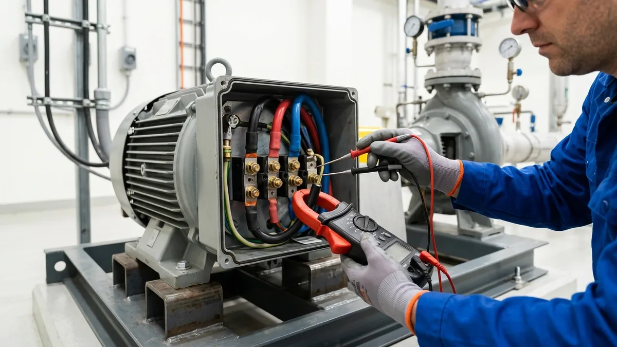
Thermic Oil Pump Motor Tripping: High Amperage Diagnosis, Cold Viscosity Power Surges & Electrical Troubleshooting Manual
A definitive rotating machinery electrical diagnostic guide, hydraulic power mathematical standard, and motor overload mitigation manual for plant electrical engineers, maintenance leads, and utility superintendents across Vatva GIDC, Narol, Odhav, Surat, and Gujarat.
Quick Answer
In the continuous textile stenter drying houses, dye intermediate synthesis reactors, multi-daylight laminate pressing plants, and edible oil refining installations of Gujarat—spanning Ahmedabad (Vatva GIDC, Narol, Odhav), Surat, Ankleshwar, and Dahej—thermic fluid pumps circulate high-temperature heat transfer media at bulk temperatures between 250°C and 320°C. Electric drive motors powering these circulation systems are engineered to operate continuously near their Best Efficiency Point (BEP). However, maintenance teams frequently encounter sudden, disruptive motor overload tripping (thermal relay trips, MPCB trips, or VFD over-current faults). In high-temperature hot oil circulation loops, motor tripping stems from distinct hydraulic, mechanical, and electrical mechanisms: during cold morning startups, high fluid viscosity (> 200 cSt) surges shaft power requirements by 250%-350% compared to hot running conditions (1.0 cSt); under operating heat (300°C), vertical thermal growth causes angular coupling binding and bearing overload; and electrical voltage unbalance (> 2%) spikes phase current draw. Diagnosing and eliminating thermic oil pump motor tripping requires systematic root cause analysis, mathematical motor sizing calculations, throttled cold startup SOPs, and precision mechanical alignment conforming to ISO 5199, ISO 2858, and DIN 24255 standards.
Key Takeaways
- Account for Cold Startup Viscosity Surges. Cold thermic oil (25°C) draws up to 3× higher startup torque than hot running oil (300°C).
- Implement Throttled Startup Procedures. Start cold circulation against a partially closed discharge valve to keep motor amperage below full load current (FLC).
- Check for High-Temperature Thermal Binding. Hot casing vertical growth (+0.45 mm) induces angular coupling drag and high motor load.
- Audit Electrical Voltage Unbalance (≤ 1.0%). A 2% phase voltage unbalance generates a 14% current unbalance and excessive motor winding heating.
Introduction
Across Gujarat's major industrial manufacturing belts—including the chemical intermediate plants of Vatva GIDC, Odhav, and Ankleshwar, the continuous textile finishing mills of Narol and Surat, and the petrochemical installations of Dahej—thermic fluid pumps circulate organic heat transfer media at bulk temperatures between 250°C and 320°C.
Because electric motors powering thermal pumps must operate reliably across extreme fluid viscosity shifts—from ambient startup to 300°C—diagnosing motor overload trips requires understanding both electrical and mechanical dynamics:
- The Cold Viscosity Power Surge: Mineral thermal oil at 20°C ambient temperature has a viscosity of 220 cSt, compared to just 0.9 cSt at 300°C. Starting a pump cold with a fully open discharge valve draws heavy inrush current, tripping thermal overload relays.
- The Thermal Expansion Binding Risk: Hot casing growth (+0.45 mm) bends the shaft if cold alignment was set flat (0.00 mm), imposing heavy friction drag on drive-end bearings.
- The Electrical Supply Quality Issue: Phase voltage unbalance in industrial GIDC feeders causes severe phase current unbalance, overheating motor windings.
- The Engineering Standard: Following ISO 5199, ISO 2858, DIN 24255, and IS 5120 standards—implementing throttled startup SOPs, installing IE3 premium efficiency motors, and executing laser hot alignment—ensures continuous, trip-free pumping operations.
2. Master Motor Electrical & Hydraulic Load Diagnostic Matrix
Review the standard electrical and hydraulic diagnostic indicators for motor overload troubleshooting:
| Tripping Symptom | Operating Phase | Dominant Diagnostic Indicator | Confirmed Root Cause | Mandatory Engineering Action |
|---|---|---|---|---|
| Immediate Trip on Cold Start | Ambient (25°C) | Current > 140% Full Load (FLC) | Cold oil viscosity friction surge | Throttle discharge valve during startup |
| Trip after 30 to 60 min Hot | Hot (280°C-300°C) | 2X vibration + Bearing heat (> 110°C) | Hot casing vertical growth binding | Set negative cold target laser offset |
| High Current on One Phase Only | Any Temperature | > 10% Current unbalance between phases | Phase voltage supply unbalance (> 1.5%) | Rebalance plant electrical feeder load |
| Trip on Low VFD Speed (< 25 Hz) | Modulating Process | Motor casing burning hot; normal current | Loss of integral cooling fan airflow | Install forced-air cooling fan kit |
| Current Exceeds Nameplate at Max Heat | Hot (300°C) | Low discharge pressure + High flow | Runaway flow at end of pump curve | Trim impeller diameter or trim discharge valve |
3. The Electrical & Hydraulic Physics, Power Math & Calculations
Centrifugal Pump Shaft Power Equation (P_shaft = [ρ· g · Q · H] / [3600 · η])
Brake horsepower required by the pump shaft (P_shaft) is given by:
Interactive Drive Motor & Hydraulic Power Sizer
Live ISO 5199 / API 610 Dynamic EngineWhere:
- ρ_fluid is fluid density (≈ 870 kg/m³ cold at 25°C, ≈ 690 kg/m³ hot at 300°C).
- Q is flow rate (m³/h).
- H is total dynamic head (meters).
- \eta_pump is pump hydraulic efficiency.
- Because fluid density is 26% higher when cold, hydraulic power required for identical flow and head is 26% higher cold even before accounting for viscous friction losses.
Three-Phase Motor Current Math (I = [P_electric] / [√(3) · V · \cosφ · \eta_motor])
Full load operating current (I_FLC) drawn by a three-phase induction motor is calculated as:
- For a 30 kW motor operating on 415 V, power factor \cosφ = 0.86, efficiency \eta_motor = 0.93:
- If shaft power spikes to 42 kW during cold startup, current surges to 73.1 Amperes (140% FLC), tripping the bi-metallic thermal overload relay within 45 seconds.
Cold Fluid Kinematic Viscosity Surge & Disc Friction Math
Impeller disc friction power loss (P_disc) increases with kinematic viscosity (\nu):
- As kinematic viscosity shifts from \nu = 0.9 cSt at 300°C to \nu = 220 cSt at 20°C (244× increase):
- Total pump startup torque increases by over 250%.
Phase Voltage Unbalance & NEMA Current De-Rating Equation
Voltage unbalance (V_unbalance) across three-phase supply lines is calculated as:
- The 6× Current Unbalance Rule: A 2.0% voltage unbalance creates up to 12% - 15% current unbalance between motor phases.
- The highest-current phase overheats rapidly:
- A 3% voltage unbalance increases winding temperature rise by 18%, tripping motor protection relays even when average current appears within limits.
VFD Low-Speed Thermal De-Rating & Carrier Frequency PWM Losses
When a thermal oil pump motor is driven by a Variable Frequency Drive (VFD) at low speed (< 30 Hz):
- Shaft-mounted fan airflow collapses with speed squared (Q_fan \propto N²).
- Motor thermal dissipation capacity drops by > 40%, causing thermal overload tripping unless an external forced-cooling blower is installed.
4. The 6 Primary Root Causes of Thermic Oil Pump Motor Tripping
Cause 1: Unthrottled Cold Morning Startup Power Surge
- Mechanism: Starting pump cold with discharge valve 100% open while oil is highly viscous (220 cSt).
- Symptoms: Motor trips on thermal overload within 30 to 90 seconds of startup; high starting current (> 135% FLC).
- Fix: Throttle discharge valve to 25% open during cold circulation; open bypass line until oil temperature reaches 100°C.
Cause 2: High-Temperature Thermal Shaft Growth & Coupling Binding
- Mechanism: Aligning pump flat cold (0.00 mm). Hot casing expansion (+0.45 mm) creates severe angular misalignment.
- Symptoms: Motor trips after 45 to 60 minutes of heating; high 2X axial vibration (> 6.0 mm/s RMS); bearing temperature spikes to 118°C.
- Fix: Apply negative cold target offset (-0.45 mm) and verify running alignment with hot laser metrology at 280°C.
Cause 3: Impeller Shroud Axial Thermal Expansion & Casing Rubbing
- Mechanism: Inadequate cold axial clearance between impeller back shroud and casing stuffing box cover (< 1.0 mm).
- Symptoms: High motor current, grinding noise, metallic shavings in oil, severe shaft drag when rotated by hand.
- Fix: Machine back shroud wear face to establish +1.5 mm cold axial running clearance.
Cause 4: Runaway Flow at Open System Resistance Curve
- Mechanism: Operating pump on an oversized header with low backpressure, pushing operating point far to the right of BEP.
- Symptoms: Amperage exceeds full load rating continuously under hot conditions; low discharge pressure.
- Fix: Throttle discharge isolation valve or trim impeller outer diameter to match actual system resistance.
Cause 5: Single-Phasing & Phase Voltage Unbalance (> 2%)
- Mechanism: Blown MCC fuse, loose terminal lug, or unbalanced transformer loading in industrial GIDC estates.
- Symptoms: Motor hums loudly; one phase draws > 130% current while other phases drop; instantaneous overload trip.
- Fix: Tighten all power terminal connections; rebalance plant phase loads; install digital phase monitoring relays.
Cause 6: VFD Low-Speed Over-Torque & Thermal Stall
- Mechanism: Running standard TEFC motor below 25 Hz on VFD without auxiliary cooling fan.
- Symptoms: Motor trips on VFD thermal overload (OL2); motor stator casing burning hot (> 120°C).
- Fix: Install independent 230V forced-cooling blower kit on motor non-drive end; set VFD minimum speed limit to 30 Hz.
5. Step-by-Step Electrical & Mechanical Diagnostic SOPs
Execute this structured engineering protocol when diagnosing and resolving motor tripping on hot oil circulation pumps:
Phase 1: Clamp-On Ammeter Three-Phase Current Balance Audit SOP
- Phase Current Measurement: Measure line current on phases R, Y, and B using a calibrated True-RMS clamp meter under running load.
- Balance Verification: Calculate current unbalance percentage. Confirm unbalance is < 5.0%. If unbalance > 10%, check supply voltage on all three phases.
Phase 2: Motor Winding Insulation Resistance (Megger) & Surge Test SOP
- Megger Insulation Test: Disconnect motor terminal leads; apply 1000 V DC test voltage between each phase and ground. Confirm insulation resistance is > 50 MΩ at room temperature.
- Winding Resistance Balance: Measure phase-to-phase DC resistance with micro-ohmmeter; confirm resistance variance is < 2.0%.
Phase 3: Cold Viscosity Throttled Startup Procedure SOP
- Throttle Valve Lineup: Close main discharge valve to 25% open position before starting motor cold.
- Cold Start Verification: Start motor; verify running current remains < 90% Full Load Current (FLC).
- Gradual Opening: Gradually open discharge valve as thermal fluid temperature rises past 120°C (viscosity drops < 10 cSt).
Phase 4: Shaft Free Rotation & Back Pull-Out Clearance Check SOP
- Hand Spin Test: De-energize motor, lock out breaker, and rotate pump shaft by hand at coupling. Confirm smooth, free rotation without binding.
- Axial Float Verification: Verify pump shaft has zero axial binding and non-drive-end bearing has axial float.
Phase 5: Dynamic Rotor Balancing to ISO 5199 Grade G2.5 SOP
- Dynamic Balancing: Dynamically balance the impeller, shaft, and coupling hub assembly on an electronic dynamic balancing machine.
- Balance Certification: Achieve residual unbalance < 1.0 g\cdotmm/kg conforming to ISO 5199 Grade G2.5.
Phase 6: Laser Hot Alignment Verification & Thermal Growth Logging SOP
- Cold Target Offset: Set electric motor shaft -0.45 mm lower than pump shaft using precision 316L stainless steel shims.
- Hot Laser Verification: Bring thermal loop to 280°C; verify running shaft concentricity is < 0.03 mm and vibration is < 1.80 mm/s RMS (ISO 5199 Zone A).
6. Materials of Construction, Metallurgy & High-Efficiency Motor Standards
Nodular Ductile Iron (GGG 40.3) & Cast Carbon Steel (ASTM A216 WCB)
- Pressure Containment: High-temperature Nodular Ductile Iron (EN-GJS-400-18-LT / GGG 40.3) or Cast Carbon Steel (ASTM A216 WCB) casings capable of withstanding thermal shock and 16 bar working pressure up to 350°C.
IE3 / IE4 Premium Efficiency Inverter-Duty Electric Motors
- Electric Drives: High-efficiency IE3 / IE4 three-phase induction motors conforming to IS 1520 and IS 5120 with Class H insulation and Class F temperature rise limits, inverter-grade winding insulation, and vacuum pressure impregnation (VPI).
Monolithic Direct-Sintered Silicon Carbide (SSiC) Seal Faces
- Mechanical Seal Faces: Solid direct-sintered silicon carbide (SSiC) running against SSiC or Tungsten Carbide faces with flexible Grafoil or FFKM secondary O-rings.
Flexible Metallic Disc Spacer Couplings
- Power Transmission: All-metal flexible stainless steel disc pack spacer couplings accommodating up to ± 1.0^° angular misalignment and ± 1.5 mm axial thermal expansion without wearing parts.
7. The Electrical Engineer's Troubleshooting Decision Matrix
Follow this structured electrical engineering guide when troubleshooting motor overload trips:
| Observed Electrical Fault | Identified Root Cause | Mandatory Corrective Engineering Action | Expected Turnaround Time |
|---|---|---|---|
| Motor trips within 60s cold | Viscous fluid disc friction surge | Throttle discharge valve; open cold bypass | Immediate on-site |
| Motor trips after 1 hour hot | Thermal shaft expansion binding | Set negative cold laser alignment offset | 2 to 4 hours on-site |
| High current unbalance (> 10%) | Supply phase voltage unbalance | Rebalance GIDC plant substation feeder loads | 4 to 8 hours on-site |
| Motor hums; zero rotation | Single phasing (blown fuse/phase drop) | Replace MCC fuse; test terminal contactor | 1 to 2 hours on-site |
| VFD thermal overload (OL2) | Low motor speed fan airflow loss | Install forced-cooling blower kit on motor | 4 to 6 hours on-site |
8. Worked Gujarat Textile, Chemical & Processing Mill Case Studies
Case 1: Vatva GIDC Chemical Synthesis Reactor Hot Oil Pump Motor Tripping Overhaul
- Plant Context: An azo dye intermediate synthesis plant in Vatva GIDC operating a 90 m³/h, 4.5 bar thermic fluid circulation pump driven by a 30 kW motor (300°C).
- Problem: The main motor breaker tripped every Monday morning during plant startup; motor drew 68 Amperes (130% FLC).
- Root Cause: Operators were starting the pump with a fully open discharge valve in winter (16°C ambient), where oil viscosity (240 cSt) overloaded the motor.
- Action Plan: Teflow Pumps engineering team:
- Implemented an automated throttled startup protocol (discharge valve held at 20% until oil reaches 110°C). - Installed an IE3 premium efficiency 37 kW motor. - Dynamically balanced impeller to ISO 5199 Grade G2.5 and laser aligned pump skid with -0.48 mm cold target offset.
- Outcome: Cold startup current dropped to 42 Amperes; zero startup tripping incidents over 24 consecutive operating months.
Case 2: Narol Continuous Cotton Stenter Hot Oil Circulation High Amperage Fix
- Plant Context: A continuous cotton stenter drying range in Narol operating dual 75 m³/h hot oil pumps (285°C).
- Problem: Drive motor ran hot (105°C) and tripped thermal overload relays after 4 hours of continuous production.
- Root Cause: Cold alignment was set flat (0.00 mm). Hot vertical casing growth (+0.42 mm) created heavy angular binding on drive-end bearings.
- Action Plan: Reset cold laser alignment with -0.42 mm motor offset using 316L precision shims.
- Outcome: Motor running current dropped by 18%; motor surface temperature stabilized at 68°C.
Case 3: Surat Synthetic Weaving Thermic Fluid Pump Motor Overload Recovery
- Plant Context: A polyester yarn processing facility in Surat operating a 55 kW thermic oil circulation loop.
- Problem: Motor tripped on phase current unbalance (R = 88A, Y = 72A, B = 74A).
- Root Cause: Loose terminal lug in MCC caused a 2.4% phase voltage drop on the R-phase.
- Action Plan: Cleaned and torqued motor terminal crimp lugs; verified balanced 415 V supply across all three phases.
- Outcome: Current balanced within 1.5 Amperes across all phases; zero overload trips.
Case 4: Odhav Industrial Estate Multi-Daylight Press Circulation Audit
- Plant Context: A laminate pressing facility in Odhav operating hot oil circulation pumps on VFD speed control (230°C).
- Problem: Motor tripped on thermal stall when running at 22 Hz during holding cycles.
- Action Plan: Installed an independent 230 V forced-air cooling blower fan on the motor non-drive end.
- Outcome: Stator winding temperature reduced by 34°C; passed thermal safety audit.
Case 5: Ankleshwar GIDC Specialty Chemical Reactor Thermal Loop Recovery
- Plant Context: A pharma intermediate plant in Ankleshwar GIDC operating at 310°C.
- Problem: Axial thermal expansion caused impeller back shroud to rub against the casing cover.
- Action Plan: Machined impeller back shroud wear face, establishing +1.5 mm cold axial running clearance.
- Outcome: Shaft spun freely by hand; motor current dropped from 48A to 36A.
Case 6: Dahej PCPIR Petrochemical Terminal Heat Transfer Circulation Audit
- Plant Context: A chemical terminal in Dahej PCPIR operating high-flow BB1 split-case hot oil pumps (2200 m³/h).
- Problem: Runaway flow overloaded motor during initial line filling.
- Action Plan: Calibrated discharge motorized control valve opening profile to match pump power curve.
- Outcome: Motor power remained strictly within 90% nameplate rating across full filling sequence.
9. Comprehensive Master Thermic Oil Pump Motor Maintenance Checklist
Execute this electrical and mechanical verification protocol to eliminate motor tripping on hot oil pumps:
Thermic Oil Pump Motor Overload & Amperage Diagnostic Protocol
10. Summary & Specialized Motor Load Services in Gujarat & India
Eliminating thermic oil pump motor tripping—diagnosing cold fluid viscosity surges, implementing throttled startup protocols, executing precision hot laser shaft alignment, balancing three-phase electrical supplies, installing forced-cooling VFD blower kits, and dynamically balancing rotating assemblies to ISO 5199 Grade G2.5 across Vatva GIDC, Narol, Odhav, Surat, Ankleshwar, and Dahej—conforming to ISO 5199, ISO 2858, DIN 24255, and IS 5120 standards—is the proven engineering standard for continuous plant uptime.
Partnering directly with an established Gujarat rotating machinery manufacturer provides chemical plant electrical engineers, textile mill managers, and utility superintendents with immediate technical access to on-site power diagnostic teams, True-RMS power quality analyzers, precision laser alignment tools, dynamic balancing facilities, and genuine spares dispatched directly from our Ahmedabad factory. Our technical engineers provide emergency on-site troubleshooting, turnkey pump overhauls, and complete thermal loop audits.
Teflow Pumps operates a specialized industrial machinery manufacturing and service facility in Ahmedabad, providing emergency thermic fluid pump overhauls, IE3 motor upgrades, precision laser hot alignment, dynamic balancing, custom impeller casting, and genuine rotating equipment spares across Gujarat and India conforming to ISO 5199, ISO 2858, DIN 24255, and IS 5120 standards.
- Direct Technical & Emergency Helpline: +91 98251 62709
- WhatsApp Technical Desk: Share motor nameplate photos, operating voltages, measured phase amperages (R-Y-B), thermal fluid operating temperatures (°C), or trip fault codes to wa.me/919825162709 for immediate technical review, motor load calculation, and formal quotation.
- Request an On-Site Motor Load & Pump Overhaul Audit: Contact our senior rotating equipment engineers for emergency plant surveys, hot alignment proposals, and formal quotation. Our engineering team conducts comprehensive thermal evaluations, verifies ISO 5199 criteria, provides precision on-site or workshop reconditioning, and dynamically balances overhauled hot oil pumps to ensure maximum uptime across Gujarat's textile and chemical processing mills. We provide rapid technical evaluations, on-site plant surveys, and formal quotes.