
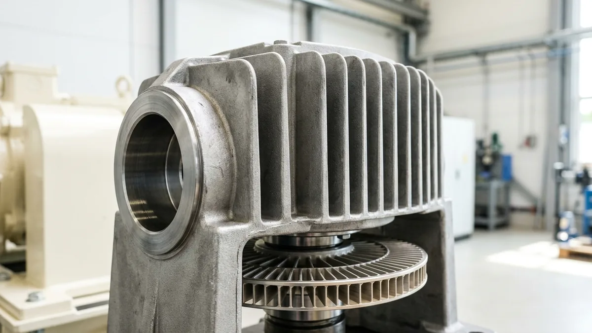
Thermic Fluid Pump Overheating: 9 Root Causes, Thermal Physics & Field Engineering Fixes
A definitive high-temperature pumping diagnostic manual, heat dissipation engineering standard, and preventive maintenance protocol for utility engineers, plant superintendents, and textile process leads across Narol, Vatva GIDC, Odhav, Surat, and Gujarat.
Quick Answer
In the intensive textile dyeing houses, stenter processing plants, chemical reactor halls, plywood laminating facilities, and edible oil refineries of Gujarat—spanning Ahmedabad (Narol, Vatva GIDC, Odhav), Surat, Ankleshwar, and Vapi—thermic fluid pumps circulate synthetic and mineral heat transfer oils at temperatures ranging from 250°C to 350°C. While the process casing handles extreme heat, the air-cooled intermediate bracket, mechanical seal chamber, and bearing housing are designed to maintain operating temperatures below 95°C - 105°C via natural convective cooling fins. When a thermic fluid pump overheats—exhibiting bearing skin temperatures spiking above 120°C, blistering bracket paint, smoking seal quench chambers, or repeated mechanical seal face failure—plant utility engineers face immediate risks: fluid carbonization (coking), catastrophic seal blowout, thermal seizure, and fire hazards. Rapidly diagnosing and remediating overheating requires understanding the 9 primary mechanical and thermal root causes: from carbon sludge fouling the cooling jacket and thermal growth angular misalignment to grease carbonization and closed bypass loops.
Key Takeaways
- Monitor Bearing & Bracket Temperature Thresholds. Bearing housings must not exceed 95°C - 105°C even with 320°C oil circulating.
- Inspect Intermediate Bracket Cooling Fins Regularly. Cotton lint, carbon dust, and grease coat cooling fins, cutting heat dissipation by > 60%.
- Perform Hot Alignment with Thermal Growth Offsets. Cold alignments must incorporate manufacturer vertical thermal growth offsets (+0.25 mm).
- Prevent Deadheaded Fluid Boiling & Coking. Maintain a continuous minimum thermal loop bypass flow (≥ 20% of Best Efficiency Point).
Introduction
In Gujarat's industrial processing clusters—from the intensive textile processing, bleaching, and stenter lines in Narol and Surat to the chemical intermediate reactors of Vatva GIDC, Odhav, and Ankleshwar—thermic fluid pumps are the beating heart of high-temperature heating loops. Operating without water jackets, these specialized air-cooled pumps utilize long intermediate throttle brackets with cast cooling fins to drop fluid temperatures from 300°C at the pump volute casing down to below 80°C - 95°C at the drive-end ball bearings.
When this thermal gradient breaks down, plant maintenance teams face severe operating emergencies:
- The Safety and Fire Threat: Thermic fluid leaking from an overheated mechanical seal onto hot piping insulation can auto-ignite, presenting a grave industrial plant fire hazard.
- The Production Interruption: Unplanned pump trips on high bearing temperature halt multi-color textile printing, stenter drying, and chemical synthesis batches, costing hundreds of thousands of rupees per downtime hour.
- The Engineering Standard: Conforming to ISO 5199, ISO 2858, and DIN 24255 standards—incorporating precision hot laser alignment, high-temperature C3 bearing clearances, direct-sintered silicon carbide mechanical seals, and dynamic rotor balancing—ensures reliable continuous hot oil circulation with zero thermal breakdown.
2. Master Thermic Fluid Pump Thermal Operating Thresholds Matrix
Review the standard temperature zones, design limits, and alarm thresholds across a typical air-cooled thermic fluid pump:
| Pump Component Zone | Typical Operating Fluid Temp | Normal Skin Surface Temp | Alarm & Trip Threshold | Key Thermal Protection Mechanism |
|---|---|---|---|---|
| 1. Volute Casing & Suction | 250°C - 350°C | 240°C - 340°C | > 360°C (Fluid Max) | Ductile iron GGG 40.3 casing stress limits |
| 2. Intermediate Throttle Bracket | 180°C - 240°C | 120°C - 160°C | > 180°C (Finned Area) | Long throttle bush + cast cooling fins |
| 3. Mechanical Seal Chamber | 90°C - 130°C | 80°C - 110°C | > 135°C (Seal Face Danger) | Quench chamber + natural heat dissipation |
| 4. Drive-End Bearing Housing | Ambient to 80°C | 65°C - 90°C | > 105°C (Grease Breakdown) | C3/C4 internal clearance + synthetic grease |
3. The Thermal Physics, Convective Cooling Math & Calculations
Air-Cooled Intermediate Bracket Heat Transfer Math (Q = h · A · ΔT)
Heat conducted along the pump shaft and intermediate bracket is dissipated into ambient air by natural or forced convection:
Where:
- h_conv is the convective heat transfer coefficient (15 - 25 W/m²\cdotK for natural air circulation).
- A_fins is the extended surface area of the cast cooling fins on the bracket.
- When cotton lint, chemical grime, or oil dust coats the cooling fins, the effective h_conv drops by > 60%, driving up bearing housing temperatures by 30°C - 45°C.
Shaft Axial & Vertical Thermal Growth Equation (ΔL = α· L · ΔT)
As the pump casing heats from ambient (30°C) to full operating temperature (300°C), thermal expansion occurs:
Where:
- α_iron ≈ 12 × 10^-6 m/m·°C.
- For a centerline height H = 200 mm and ΔT = 270°C:
- If cold laser alignment is set perfectly flat (0.00 mm offset), the pump centerline will rise by over 0.60 mm relative to the cool electric motor, imposing massive angular misalignment, 2X vibration, and catastrophic bearing overheating.
Fluid Film Boundary Layer Temperature & Cracking Kinetics
Thermal oil in contact with hot internal surfaces undergoes thermal cracking when film temperatures exceed critical limits:
- If bulk oil temperature is 300°C and fluid flow stagnates near the mechanical seal chamber, the stagnant oil film temperature spikes past 360°C, cracking into volatile gases and solid carbon residue (coke).
- Carbon flakes accumulate in the mechanical seal spring pocket and throttle bush, jamming the seal face and restricting thermal dissipation.
Bearing Internal Clearance Shrinkage & High-Temperature Grease Breakdown
As heat conducts along the shaft into the inner bearing race (T_inner ≈ 110°C) while the outer housing is cooled by ambient air (T_outer ≈ 70°C):
- Standard clearance (CN) ball bearings lose all radial clearance, creating severe internal metal-to-metal preload.
- Using C3 (or C4 for extreme heat) radial internal clearance bearings is mandatory to prevent thermal pinching and catastrophic bearing seizure.
Minimum Thermal Bypass Flow Velocity & Boiling Head Loss
To prevent localized boiling in the pump volute:
- Maintain a minimum thermal loop circulation velocity (v ≥ 2.5 m/s) across the heater coils and pump suction.
- Minimum continuous bypass flow must be at least 20% - 25% of Best Efficiency Point (BEP) flow during low-load or warmup cycles.
4. The 9 Primary Root Causes of Thermic Fluid Pump Overheating
Cause 1: Coking & Thermal Degradation Sludge Blocking Bracket Heat Dissipation
- Mechanism: Degraded thermic fluid with high carbon residue (> 1.0% CCR) deposits a baked insulating carbon crust inside the throttle bracket and seal chamber.
- Diagnostic Symptom: Throttle bracket is blistering hot (> 190°C); seal faces are heavily coked and leaking.
- Field Fix: Flush system with chemical cleaning solvent, dismantle pump, chemically descale bracket, and replenish with fresh synthetic thermal oil.
Cause 2: Thermal Growth Shaft Misalignment & Radial Bearing Binding
- Mechanism: Aligning pump and motor cold without accounting for the +0.30 - +0.65 mm vertical thermal expansion of the hot pump.
- Diagnostic Symptom: Bearing temperature spikes within 30 minutes of heating up; high 2X axial vibration (> 4.5 mm/s RMS).
- Field Fix: Perform cold pre-alignment with intentional negative motor offset, verify alignment with hot laser alignment check at 300°C.
Cause 3: Cooling Fin Airflow Choking by Cotton Lint & Process Dust
- Mechanism: In textile mills, airborne cotton fluff and fly ash settle between the cast cooling fins, forming a thermal blanket.
- Diagnostic Symptom: Clean casing with hot bearing housing; zero air velocity between fin channels.
- Field Fix: Establish weekly de-ashing protocols using dry compressed air or high-pressure steam cleaning to keep fin channels open.
Cause 4: Mechanical Seal Face Dry-Running & Quench Evaporation
- Mechanism: Thermal oil vaporizes at the narrow seal face interface (0.5 µm gap) or atmospheric quench chamber dries out.
- Diagnostic Symptom: Squealing acoustic noise from seal area; rapid face heat checking and cracked silicon carbide faces.
- Field Fix: Install monolithic direct-sintered SSiC vs SSiC faces; ensure continuous water or high-temp oil quench is maintained in Plan 62 chamber.
Cause 5: Bearing Grease Carbonization & Loss of C3/C4 Clearance
- Mechanism: Using standard mineral-based EP2 grease (drops point < 180°C) instead of high-temperature synthetic polyurea or fluorinated grease.
- Diagnostic Symptom: Grease hardens into a black crumbly solid; bearing cage fractures due to unlubricated ball skidding.
- Field Fix: Install high-temperature C3 deep groove ball bearings packed with synthetic grease rated for continuous 180°C service.
Cause 6: Throttled Discharge / Deadheaded Operation (Fluid Boiling)
- Mechanism: Modulating control valves on textile stenter machines close completely while the circulation pump runs with no bypass.
- Diagnostic Symptom: Discharge pressure fluctuates wildly; pump casing emits rumbling cavitation noises as fluid flashes to vapor.
- Field Fix: Install a continuous, unthrottled minimum flow bypass line (20% BEP) back to the thermic fluid expansion tank.
Cause 7: Reverse Impeller Rotation Generating Excessive Hydraulic Friction
- Mechanism: Wiring phase reversal after electrical panel maintenance causing backward impeller rotation.
- Diagnostic Symptom: Pump delivers < 40% head and flow while drawing high motor amperage and generating severe internal churning heat.
- Field Fix: Check rotation arrow cast on volute; reverse any two phase leads at the motor terminal box.
Cause 8: Low Circulation Flow Velocity Accelerating Oil Cracking
- Mechanism: Undersized circulation piping or excessive loop resistance dropping flow velocity below 1.5 m/s.
- Diagnostic Symptom: High ΔT across heater (> 35°C); rapid oil degradation and high pump casing skin temperatures.
- Field Fix: Optimize system hydraulic resistance, clean inline strainers, or trim impeller to increase flow rate.
Cause 9: Rigid Piping Thermal Expansion Imposing Severe Casing Strain
- Mechanism: Hot process piping expanding without adequate expansion bellows or flexible pipe loops, pushing against pump flanges.
- Diagnostic Symptom: Loosened flange bolts bind shaft rotation; severe coupling angular misalignment under hot conditions.
- Field Fix: Install 2-ply stainless steel high-temperature expansion bellows and reinforce pipe anchor supports.
Interactive Pump Failure Root-Cause Diagnostic Navigator
ISO 10816 / API 682 Step-by-Step Triage FlowClassic NPSHa starvation or thermodynamic vapor flashing at first-stage impeller eye (NPSHa < NPSHr + 1.5m).
Check suction strainer differential pressure (ΔP > 0.35 bar indicates clogging); audit deaerator/tank static height and fluid vapor pressure.
Clean suction strainer; elevate suction feed vessel or increase suction pipe diameter to lower flow velocity below 1.2 m/s; trim impeller or fit high-Nss inducer.
5. Step-by-Step Field Diagnostic & Overhaul SOPs
Execute this structured engineering protocol when troubleshooting or overhauling an overheated hot oil pump:
Phase 1: Infrared Thermographic Thermal Profile Mapping SOP
- Infrared Thermography: Use a calibrated thermal imaging camera to record temperature profiles across 4 zones: volute casing, intermediate throttle bracket, seal chamber, and bearing housing.
- Gradient Verification: Verify that temperature drops by at least 120°C between casing and bearing housing. If the bracket shows an unbroken high temperature (> 180°C), suspect coking or cooling fin blockage.
Phase 2: Cooling Fin & Fan Impeller Airflow De-Ashing SOP
- De-Ashing Fins: Blow dry compressed air (6 bar) across all intermediate bracket fin channels to dislodge cotton lint, carbon dust, and grease films.
- Fan Verification: Check that the shaft-mounted cooling fan (if fitted) is securely keyed and spinning in the correct orientation to draw ambient air across the fins.
Phase 3: Thermal Loop Bypass Flow & Differential Pressure Audit SOP
- Pressure Audit: Measure suction (P_s) and discharge (P_d) pressures with calibrated high-temperature gauges.
- Bypass Verification: Confirm that the minimum flow bypass line is open and circulating at least 20% of rated BEP flow during low-load heater firing.
Phase 4: Hot Laser Alignment & Thermal Growth Compensation SOP
- Cold Setup: Set cold alignment with intentional vertical offset (motor set lower by +0.25 to +0.45 mm depending on pump centerline height).
- Hot Check: Run the thermal loop up to 280°C - 300°C for 2 hours; stop motor and immediately perform hot alignment verification with laser tool. Confirm offset < 0.03 mm.
Phase 5: Seal Chamber Carbon Descaling & Mechanical Seal Reconditioning SOP
- Strip Seal Chamber: Extract cartridge mechanical seal; immerse in chemical solvent to dissolve carbon sludge.
- Face Inspection: Inspect monolithic silicon carbide faces for thermal heat checking or pitting. Lap faces to < 2 light bands flatness (0.6 µm).
- Quench Setup: Flush and refill the Plan 62 quench pot with clean thermal oil or high-temperature barrier fluid.
Phase 6: Rotor Balancing to ISO 5199 Grade G2.5 & High-Temp FAT SOP
- Dynamic Balancing: Dynamically balance the reconditioned impeller and shaft assembly on an electronic dynamic balancing machine to ISO 5199 Grade G2.5 (< 1.0 g\cdotmm/kg).
- Reassembly & Run: Install C3 internal clearance high-temperature bearings, fill with synthetic polyurea grease, and conduct 2-hour vibration test (v_RMS < 1.80 mm/s Zone A).
6. Materials of Construction, Metallurgy & High-Temperature Sealing
High-Grade Ductile Iron (GGG 40.3) & Cast Steel (ASTM A216 WCB) Casings
- Pressure Containment: High-temperature Nodular Ductile Iron (EN-GJS-400-18-LT / GGG 40.3) or Cast Carbon Steel (ASTM A216 WCB) casings capable of withstanding thermal shock and 16 bar working pressure up to 350°C.
High-Temperature C3 / C4 Radial Internal Clearance Bearings
- Bearings: Deep groove ball and cylindrical roller bearings manufactured with stabilized heat-treated rings (S1/S2 thermal stabilization up to 250°C) and C3/C4 radial internal clearances.
Monolithic Direct-Sintered Silicon Carbide (SSiC) & Tungsten Carbide Seals
- Mechanical Seal Faces: Solid direct-sintered silicon carbide (SSiC) running against SSiC or Tungsten Carbide faces with flexible Grafoil or FFKM secondary O-rings.
Flexible Grafoil & Spiral Wound High-Temperature Gaskets
- Casing Sealing: Pure flexible exfoliated graphite (Grafoil) die-formed rings and SS316 spiral-wound gaskets with flexible graphite filler for leak-tight casing joints.
7. The Utility Engineer's Thermal Maintenance Decision Framework
Follow this structured engineering guide when determining corrective actions for overheated pumps:
| Observed Thermal Symptom | Identified Root Cause | Mandatory Corrective Action | Turnaround Time |
|---|---|---|---|
| Bearing housing 105°C - 120°C | Lint on fins + cold alignment error | Blow out cooling fins; execute laser hot alignment | 2 to 4 hours on-site |
| Mechanical seal smoking / dripping | Seal face thermal coking / quench dry | Clean seal chamber; lap SSiC faces; refill quench | 6 to 12 hours on-site |
| High 1X & 2X vibration (> 4.5 mm/s) | Rotor unbalance + shaft thermal runout | Workshop dynamic balancing to ISO 5199 Grade G2.5 | 24 to 48 hours workshop |
| Casing rumbling & cavitation noise | Deadheaded flow / closed stenter bypass | Open 20% minimum thermal bypass line immediately | Immediate plant fix |
8. Worked Gujarat Textile, Chemical & Processing Mill Case Studies
Case 1: Narol Textile Processing Mill Thermic Oil Circulation Pump Overhaul
- Plant Context: A large cotton printing and stenter processing mill in Narol operating a 120 m³/h, 4.5 bar thermic fluid pump circulating synthetic oil at 290°C.
- Problem: Drive-end bearing temperature reached 128°C; pump tripped on thermal overload twice weekly, interrupting fabric processing.
- Root Cause: Cotton lint had choked 80% of the cooling fin channels, and mineral grease had carbonized inside the standard-clearance (CN) bearings.
- Action Plan: Teflow emergency service crew:
- De-ashed cooling fins with high-pressure steam and compressed air. - Replaced bearings with SKF C3 high-temperature ball bearings packed with synthetic polyurea grease. - Performed hot laser alignment accounting for +0.32 mm vertical growth.
- Outcome: Bearing skin temperature dropped to a stable 78°C; zero pump trips over 18 consecutive months.
Case 2: Vatva GIDC Dye Manufacturing Plant Hot Oil Pump Bearing Failure Fix
- Plant Context: A synthetic dye reactor facility in Vatva GIDC operating a 65 m³/h hot oil pump at 315°C.
- Problem: Repeated mechanical seal face cracking every 3 weeks with heavy carbon crusting.
- Root Cause: Stagnant thermal oil in the seal chamber cracked into carbon flakes due to an unvented dead-end seal cavity.
- Action Plan: Installed an API Plan 62 external quench system with circulating synthetic heat transfer fluid; fitted monolithic direct-sintered SSiC vs SSiC faces.
- Outcome: Seal operating life extended beyond 22 months with zero face leakage.
Case 3: Surat Synthetic Weaving Unit Thermic Fluid Pump Coking Remediation
- Plant Context: A yarn texturizing and heat-setting unit in Surat operating dual thermic fluid heaters (275°C).
- Problem: Flow rate dropped from 85 m³/h down to 52 m³/h; pump casing ran extremely hot (> 330°C).
- Action Plan: Flushed thermic loop with organic solvent; overhauled pump to remove baked carbon deposits; balanced impeller to ISO 5199 Grade G2.5.
- Outcome: Full 85 m³/h circulation flow restored; passed energy efficiency audit.
Case 4: Odhav Industrial Estate Plywood Press High-Temp Pump Realignment
- Plant Context: A multi-daylight hydraulic plywood pressing plant in Odhav operating a 45 m³/h hot oil circulation loop (240°C).
- Problem: Severe 2X vibration (5.8 mm/s RMS) and rapid coupling elastomer destruction.
- Action Plan: Laser aligned pump skid with intentional cold thermal offset; replaced rigid pipe spools with stainless steel expansion bellows.
- Outcome: Hot running vibration reduced to 0.95 mm/s RMS (Zone A).
Case 5: Ankleshwar GIDC Specialty Chemical Reactor Hot Oil Pump Overhaul
- Plant Context: A pharma intermediate facility in Ankleshwar GIDC operating a hot oil pump on an esterification reactor (280°C).
- Problem: Sudden bearing seizure during peak summer operations (45°C ambient).
- Action Plan: Installed C4 internal clearance bearings; renewed throttle bush to OEM clearance; dynamic balanced rotor.
- Outcome: Pump ran continuously throughout summer with bearing temperatures stabilized at 82°C.
Case 6: Vapi Industrial Park Bitumen Transfer Pump Thermal Recovery
- Plant Context: A modified bitumen emulsion plant in Vapi operating jacketed hot oil booster pumps (260°C).
- Problem: High motor amperage and casing overheating due to reverse rotation after wiring repair.
- Action Plan: Verified phase sequence, reversed motor leads, and calibrated thermal relief valves.
- Outcome: Amperage dropped by 38%; casing temperatures returned to normal operating range.
9. Comprehensive Master Thermic Fluid Pump Preventive Maintenance Checklist
Execute this maintenance verification protocol to prevent thermic fluid pump overheating:
Thermic Fluid Pump Preventive Maintenance & Thermal Protocol
10. Summary & Emergency Thermic Fluid Pump Services in Gujarat & India
Resolving thermic fluid pump overheating—diagnosing coking deposits, restoring cooling fin heat dissipation, executing precision hot laser alignment, dynamically balancing rotating assemblies to ISO 5199 Grade G2.5, and fitting monolithic silicon carbide mechanical seals across Narol, Vatva GIDC, Odhav, Surat, Ankleshwar, and Vapi—conforming to ISO 5199, ISO 2858, and DIN 24255 standards—is the proven engineering standard for industrial reliability.
Partnering directly with an established Gujarat rotating machinery manufacturer provides textile mill managers, utility superintendents, and process engineers with immediate technical access to on-site thermal diagnostic teams, infrared cameras, laser alignment tools, precision CNC machining, dynamic balancing facilities, and genuine spares dispatched directly from our Ahmedabad factory. Our technical engineers provide emergency on-site troubleshooting, turnkey pump overhauls, and complete thermal loop audits.
Teflow Pumps operates a specialized industrial machinery manufacturing and service facility in Ahmedabad, providing emergency thermic fluid pump overhauls, high-temperature mechanical seal replacements, precision dynamic balancing, laser alignment, custom impeller casting, and genuine rotating equipment spares across Gujarat and India conforming to ISO 5199, ISO 2858, DIN 24255, and IS 5120 standards.
- Direct Technical & Emergency Helpline: +91 98251 62709
- WhatsApp Technical Desk: Share thermal imaging photos, bearing temperature readings (°C), operating oil temperatures, pump nameplate photos, or vibration spectra to wa.me/919825162709 for immediate technical review, failure diagnosis, and formal quotation.
- Request an On-Site Thermic Fluid Pump Survey & Overhaul: Contact our senior rotating equipment engineers for emergency plant surveys, hot alignment proposals, and formal quotation. Our engineering team conducts comprehensive thermal evaluations, verifies ISO 5199 criteria, provides precision on-site or workshop reconditioning, and balances overhauled hot oil pumps to ensure maximum uptime across Gujarat's textile and chemical processing mills. We provide rapid technical evaluations, on-site plant surveys, and formal quotes.