
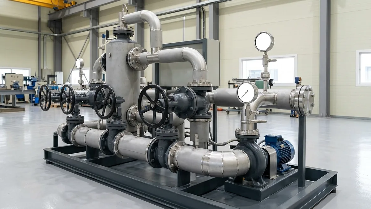
Thermic Fluid Heater Pump Shutdown & Startup Checklist: Standard Operating Procedures & Maintenance Manual
A definitive high-temperature thermal loop engineering standard, cold startup degassing protocol, and controlled shutdown checklist for plant managers, utility superintendents, and maintenance leads across Vatva GIDC, Narol, Odhav, Surat, and Gujarat.
Quick Answer
In the continuous textile processing mills, chemical synthesis plants, plywood pressing factories, and edible oil refining installations of Gujarat—spanning Ahmedabad (Vatva GIDC, Narol, Odhav), Surat, Ankleshwar, and Dahej—thermic fluid heater systems circulate mineral and synthetic heat transfer media at temperatures exceeding 280°C to 320°C. The centrifugal circulation pump is the single most critical active component in the loop: if the pump stops while the heater furnace remains hot, the stagnant oil inside the heater coils rapidly cracks into solid carbon (coke), causing tube burnout, rupture, and devastating plant fires. Conversely, during a cold startup, starting the heater without proper low-temperature deaeration and moisture evaporation causes water to flash into steam at 100°C, inducing violent pump cavitation, loss of prime, and mechanical seal blowout. Establishing a strict Thermic Fluid Heater Pump Standard Operating Procedure (SOP) and Maintenance Checklist in accordance with ISO 5199, ISO 2858, and DIN 24255 standards is essential to protect plant assets, prevent thermal fluid degradation, and ensure uninterrupted production.
Key Takeaways
- Execute Controlled Moisture Degassing at 105°C - 120°C. Hold loop temperature steady with open deaeration vents until all moisture vaporizes.
- Never Shut Down the Circulation Pump Hot. Idle the thermic fluid pump continuously after burner shutdown until bulk oil drops below 80°C - 100°C.
- Limit Thermal Ramping Rates to ≤ 10°C - 15°C/hour. Prevent severe thermal shock to ductile iron pump casings and mechanical seal faces.
- Maintain Minimum Bypass Circulation Flow (≥ 20% BEP). Ensure adequate flow velocity across heater tubes during low-load operations.
Introduction
In Gujarat's major industrial manufacturing belts—from the textile finishing hubs of Narol and Surat to the chemical parks of Vatva GIDC, Odhav, Ankleshwar, and Dahej—thermic fluid heaters deliver precision process heat up to 320°C without the high pressures associated with steam boilers.
However, operating hot oil circulation systems requires strict adherence to standardized startup, shutdown, and preventive maintenance protocols:
- The Tube Burnout Risk: Turning off the circulation pump immediately when the production shift ends leaves stagnant oil inside radiant heater coils exposed to 800°C furnace refractory heat, causing rapid coking, localized hotspots, tube rupture, and catastrophic fires.
- The Cold Startup Hazard: After plant turnarounds or fluid top-ups, atmospheric moisture inevitably condenses inside storage tanks and piping. Firing the burner rapidly without holding a degassing plateau causes water droplets to flash expand into steam, resulting in violent cavitation hammering, blown pump gaskets, and shattered mechanical seal faces.
- The Engineering Standard: Following comprehensive ISO 5199, ISO 2858, and DIN 24255 operating procedures—incorporating controlled thermal ramp rates, expansion tank deaeration, hot laser alignment, and high-temperature metallurgy—ensures maximum thermal efficiency and decades of trouble-free pump reliability.
2. Master Thermic Fluid Loop Operating Phase Matrix
Review the standard operating parameters, temperature thresholds, and operator actions across each phase of thermic fluid heater operation:
| Thermal Operating Phase | Bulk Oil Temp Range | Primary Technical Objective | Mandatory Operator Action |
|---|---|---|---|
| 1. Cold Hydraulic Priming | Ambient (25°C-40°C) | Purge air; establish base loop flow | Open expansion bypass; verify motor rotation |
| 2. Moisture Degassing Phase | 105°C - 120°C | Evaporate water; vent steam pockets | Limit ramp to ≤ 10°C/hr; open deaerator vent |
| 3. Main Thermal Ramp-Up | 120°C - 300°C | Bring process up to production heat | Ramp at ≤ 25°C/hr; verify hot laser alignment |
| 4. Normal Production Run | 280°C - 320°C | Deliver stable continuous process heat | Monitor bearing temp (< 95°C) & pump ΔP |
| 5. Controlled Normal Shutdown | 300°C down to < 80°C | Dissipate furnace refractory residual heat | Extinguish burner; idle pump until T < 80°C |
| 6. Emergency Power Loss | Hot (> 250°C) | Prevent localized boiling in heater coils | Start diesel emergency circulation pump immediately |
3. The Thermal Physics, Viscosity Dynamics & Degassing Calculations
Cold Oil Viscosity Surge & Darcy-Weisbach Frictional Head Loss
At ambient startup temperatures (25°C), thermic fluids exhibit dramatically higher kinematic viscosity (\nu) than at hot operating temperatures (300°C):
- Mineral Thermal Oil Viscosity at 25°C: \nu ≈ 180 - 250 cSt (0.00022 m²/s).
- Mineral Thermal Oil Viscosity at 300°C: \nu ≈ 0.8 - 1.2 cSt (0.000001 m²/s).
Per the Darcy-Weisbach equation:
Interactive Engineering Hydraulic Sizer
Live ISO 5199 / API 610 Dynamic Engine- At cold startup, high laminar friction (f = (64) / (Re)) increases piping pressure drop by 400% - 600%, drawing high motor startup current and reducing available Net Positive Suction Head (NPSHa).
- Starting the pump with cold oil requires gradual throttle valve opening to prevent electric motor overload.
Moisture Flash Evaporation & Volume Expansion Ratio (1:1700)
When cold thermic oil containing trace dissolved or emulsified moisture reaches 100°C:
- Water flashes into steam, expanding in volume by approximately 1,700 times:
- Even 0.1% water contamination by volume (1 liter water per 1000 liters oil) creates 1,700 liters of high-pressure steam vapor, causing catastrophic pressure surges, cavitation shock waves, and mechanical seal face fracturing if not vented through the expansion tank.
Heater Refractory Radiative Heat Soak & Stagnant Oil Coking Kinetics
When a heater burner is extinguished, the ceramic refractory lining stores massive latent thermal energy:
- Refractory Core Temperature: 700°C - 900°C.
- If the circulation pump is stopped immediately, heat radiates into the stagnant oil inside the heater tubes:
- Stagnant oil cracking accelerates exponentially, forming hard carbon coke layers that permanently choke tube bores and cause subsequent tube blowout.
Thermal Dilation & Expansion Tank Sizing Equation
As thermic fluid is heated from ambient to 300°C, volumetric thermal expansion occurs:
Where:
- β≈ 0.00085 /°C (volumetric thermal expansion coefficient).
- A 10,000 liter system heated across ΔT = 260°C expands by:
- The expansion tank must remain at least 30% full cold and less than 80% full hot to prevent hot oil overflow.
Centrifugal Pump Minimum Continuous Stable Flow (MCSF)
To prevent localized vaporization inside the pump volute:
- Minimum Continuous Stable Flow (MCSF) must be maintained at ≥ 20% - 25% of Best Efficiency Point (BEP) flow at all times.
4. The 6 Critical Traps in Thermic Fluid Pump Startups & Shutdowns
Trap 1: Instant Hot Pump Shutdown Causing Heater Tube Carbonization
- Problem: Switching off the thermic fluid pump simultaneously with the main boiler burner at the end of the production shift.
- Consequence: Radiative refractory heat bakes the stationary oil inside heater coils into coke, causing tube overheating and fire.
- Standard Protocol: Keep the circulation pump running for at least 60 to 90 minutes post-burner trip until bulk oil temperature falls below 80°C.
Trap 2: Rapid Thermal Ramping Leading to Violent Steam Cavitation
- Problem: Ramping heater temperature rapidly (> 40°C/hr) from ambient through the boiling point of water.
- Consequence: Moisture flashes into steam, destroying pump suction head, causing violent rattling, and shattering silicon carbide seal faces.
- Standard Protocol: Hold system temperature at 105°C - 120°C with open deaeration vent valves until moisture boiling ceases.
Trap 3: Cold Alignment Distortion Without Thermal Growth Offsets
- Problem: Aligning the cold pump and motor shafts flat (0.00 mm offset) during maintenance overhauls.
- Consequence: At 300°C, the pump casing centerline expands upward by +0.35 to +0.65 mm, imposing destructive angular misalignment.
- Standard Protocol: Apply intentional vertical cold offset or perform mandatory hot laser alignment verification at 280°C.
Trap 4: Expansion Tank Overflow from Accelerated Thermal Dilation
- Problem: Overfilling the expansion tank cold (> 50% level) before initial thermal ramp-up.
- Consequence: Thermal fluid expands by > 20% in volume, overflowing the expansion vent onto hot boiler roofs.
- Standard Protocol: Maintain cold expansion tank level between 25% - 35% prior to heating.
Trap 5: Trapped Air Pockets in Dead-End Process Headers
- Problem: Starting high-temperature circulation without venting high-point air valves on process user equipment (stenters, reactors).
- Consequence: Air pockets travel to the pump suction eye, causing intermittent flow collapse and loss of prime.
- Standard Protocol: Crack open all high-point vent valves during cold circulation until bubble-free oil flows.
Trap 6: Thermal Shock Face Distortion on Mechanical Seals
- Problem: Injecting cold quench water or cold makeup fluid directly into a hot running mechanical seal chamber.
- Consequence: Thermal shock shatters brittle silicon carbide or tungsten carbide seal faces.
- Standard Protocol: Use temperature-matched synthetic barrier fluids and pre-warm makeup oil before system dosing.
5. Step-by-Step Standard Operating Procedures (SOPs)
Execute these structured engineering SOPs during each operating phase:
Phase 1: Pre-Startup Inspection & Cold System Check SOP
- Expansion Tank Level: Verify cold expansion tank level is between 25% and 35% on the magnetic level gauge.
- Valve Lineup: Confirm suction and discharge isolation valves are 100% open. Confirm minimum flow bypass line is open.
- Free Rotation Check: Rotate pump shaft by hand at the coupling guard opening; verify smooth rotation without binding or rubbing.
- Lubrication & Quench: Check bearing housing grease level and verify Plan 62 mechanical seal quench reservoir is full.
Phase 2: Cold Fluid Circulation & Hydraulic Priming SOP
- Motor Bump Test: Start electric motor briefly; confirm clockwise rotation matching the casing arrow.
- Cold Circulation: Run pump with heater burner OFF for 30 minutes to circulate cold oil through all process loops.
- Air Venting: Open high-point vents and deaerator lines; purge all entrained atmospheric air until pressure gauge stabilizes.
Phase 3: Thermal Degassing & Moisture Boil-Out SOP (105°C-120°C)
- Low-Fire Burner Start: Ignite heater burner at minimum firing rate; ramp temperature at ≤ 10°C/hr.
- Degassing Hold: When temperature reaches 105°C, hold firing steady for 2 to 4 hours. Keep the deaerator vent valve cracked open to the expansion tank.
- Acoustic & Pressure Monitoring: Listen for popping sounds in the pump casing. When discharge pressure stabilizes with zero fluctuation, moisture boil-out is complete.
Phase 4: Full Operating Temperature Ramp-Up SOP (To 300°C)
- Controlled Ramp-Up: Increase heater firing rate to achieve a gradual thermal ramp of ≤ 20°C - 25°C/hr.
- Close Deaerator Vents: Close manual deaerator vent valves once temperature passes 140°C.
- Hot Laser Alignment Verification: At 280°C - 300°C, verify that bearing skin temperature remains < 95°C and vibration remains < 1.80 mm/s RMS (ISO 5199 Zone A).
Phase 5: Normal Controlled System Shutdown SOP
- Extinguish Burner: Cut fuel supply to the heater burner; shut off combustion air blowers.
- Continuous Pump Idling: Keep the thermic fluid circulation pump running continuously.
- Cool-Down Monitoring: Monitor bulk oil temperature until it drops below 80°C - 100°C (typically 60 - 90 minutes).
- Safe Pump Stop: Once temperature is below 80°C, safely switch off the electric circulation pump.
Phase 6: Emergency Tripped Shutdown Remediation SOP
- Power Outage Response: In case of total electrical grid failure, immediately engage the diesel-engine-driven emergency circulation pump or battery backup within 60 seconds to maintain flow through heater coils.
- Prevent Tube Hotspots: Keep emergency pump running until furnace refractory cools down.
6. Materials of Construction, Metallurgy & High-Temperature Sealing
Nodular Ductile Iron (EN-GJS-400-18-LT / GGG 40.3) Casings
- Pressure Casings: High-temperature Ductile Iron (GGG 40.3) or Cast Carbon Steel (ASTM A216 WCB) designed for 16 bar working pressure up to 350°C with high thermal shock resistance.
Monolithic Direct-Sintered Silicon Carbide (SSiC) Seal Faces
- Mechanical Seals: Cartridge mechanical seals featuring direct-sintered SSiC vs SSiC or Tungsten Carbide running faces with flexible Grafoil secondary packing rings.
High-Temperature C3 / C4 Synthetic Grease-Lubricated Bearings
- Bearings: S1 thermally stabilized deep groove ball bearings with C3/C4 internal radial clearance packed with high-temperature synthetic polyurea grease.
High-Purity Flexible Grafoil Gaskets
- Casing Joints: 100% pure exfoliated flexible graphite (Grafoil) die-formed rings and SS316 spiral-wound gaskets for leak-tight casing joints at 350°C.
7. The Maintenance Superintendent's Operational Decision Matrix
Follow this structured engineering framework when managing operational anomalies during startup or shutdown:
| Observed Operational Anomaly | Identified Root Cause | Mandatory Corrective Operational Action |
|---|---|---|
| Discharge pressure wildly fluctuating at 105°C | Moisture flashing into steam | Hold temp at 105°C; open deaerator vent; do not ramp |
| High motor startup current at cold start | High cold oil viscosity friction | Throttle discharge valve slightly; open cold bypass loop |
| Bearing temperature > 110°C at 300°C | Thermal growth shaft misalignment | Re-align pump skid hot using laser alignment tool |
| Expansion tank level > 85% hot | System overfilled cold | Drain excess cold oil from expansion tank drain header |
| Heater trips on low flow switch | Suction strainer clogged with carbon | Clean inline Y-strainer basket; check bypass valve |
8. Worked Gujarat Textile, Chemical & Processing Mill Case Studies
Case 1: Vatva GIDC Textile Dyehouse Thermic Fluid Heater Cold Startup Degassing
- Plant Context: A modern textile dyehouse in Vatva GIDC operating a 2.5 Million kcal/hr thermic fluid heater with a 150 m³/h circulation pump (290°C).
- Problem: During startup following annual maintenance, the pump cavitated violently at 110°C, shattering mechanical seal faces twice in 3 days.
- Root Cause: Rainwater had seeped into the underground drain tank during monsoon maintenance, contaminating the oil with 0.25% moisture. Rapid heating flashed this moisture into steam.
- Action Plan: Teflow engineering team instituted a strict degassing protocol:
- Held loop temperature at 105°C - 112°C for 6 continuous hours with open deaerator vents. - Installed new monolithic SSiC mechanical seal cartridge. - Ramped to 290°C at 15°C/hr once steam venting ceased.
- Outcome: Zero cavitation; smooth startup achieved; mechanical seal ran leak-free for over 24 consecutive operating months.
Case 2: Narol Cotton Fabric Stenter Hot Oil Pump Controlled Shutdown Overhaul
- Plant Context: A continuous cotton stenter processing mill in Narol operating dual 90 m³/h hot oil pumps (275°C).
- Problem: Frequent heater coil tube blockages and pump bearing seizures occurring after weekend plant shutdowns.
- Root Cause: Operators were switching off circulation pumps simultaneously with the boiler burner, allowing 800°C refractory heat to bake stationary oil into coke.
- Action Plan: Automated the pump control panel with an electrical interlock timer preventing pump shutdown until bulk oil temperature dropped below 80°C. Overhauled pump with C3 bearings and dynamic rotor balancing.
- Outcome: Zero heater tube coking incidents over 20 consecutive months; bearing life extended from 4 months to over 24 months.
Case 3: Surat Synthetic Weaving Unit Thermic Fluid Pump Startup Protocol
- Plant Context: A synthetic yarn heat-setting facility in Surat operating a 60 m³/h thermic oil loop.
- Problem: High startup current tripped the main motor breaker during cold morning startups in winter.
- Root Cause: High cold oil viscosity (220 cSt at 18°C) overloaded the motor when starting against an open system header.
- Action Plan: Implemented a throttled startup procedure with a dedicated cold bypass line.
- Outcome: Startup motor current reduced by 42%; zero electrical trips during winter startups.
Case 4: Odhav Industrial Estate Plywood Laminating Press Circulation Recovery
- Plant Context: A hydraulic multi-daylight laminate press in Odhav operating at 230°C.
- Problem: Pump failed to build pressure due to massive air binding in dead-end hydraulic press platens.
- Action Plan: Installed automatic high-temperature air vent valves on top platen headers and executed 45-minute cold circulation purging.
- Outcome: Full 4.2 bar differential pressure established within 15 minutes of startup.
Case 5: Ankleshwar GIDC Specialty Chemical Reactor Thermal Loop Overhaul
- Plant Context: A high-temperature reactor plant in Ankleshwar GIDC operating at 310°C.
- Problem: Chronic seal quench boiling and carbon buildup.
- Action Plan: Converted seal piping to API Plan 62 external synthetic quench and re-aligned pump skid using hot laser alignment offsets.
- Outcome: Seal skin temperature reduced by 32°C; passed environmental safety audit.
Case 6: Dahej PCPIR Petrochemical Intermediate Hot Oil Circulation Audit
- Plant Context: A petrochemical plant in Dahej PCPIR operating high-flow BB1 split-case thermic booster pumps.
- Problem: Expansion tank overflowing during emergency trip testing.
- Action Plan: Re-calculated volumetric thermal dilation and recalibrated cold expansion tank fill setpoint to 28%.
- Outcome: Zero hot oil overflow during full-load thermal expansion testing.
9. Comprehensive Master Thermic Fluid Heater Pump Maintenance Checklist
Execute this maintenance verification protocol before startup and during scheduled plant servicing:
Thermic Fluid Heater Pump Startup & Maintenance Protocol
10. Summary & Specialized Thermic Fluid Pump Services in Gujarat & India
Executing standardized thermic fluid heater pump startup and shutdown procedures—enforcing low-temperature moisture degassing plateaus, controlling thermal ramp rates, maintaining post-shutdown circulation idling, and performing precision hot laser alignment across Vatva GIDC, Narol, Odhav, Surat, Ankleshwar, and Dahej—conforming to ISO 5199, ISO 2858, and DIN 24255 standards—is the proven engineering standard for high-temperature operational reliability.
Partnering directly with an established Gujarat rotating machinery manufacturer provides textile mill managers, utility superintendents, and chemical plant engineers with immediate technical access to specialized on-site diagnostic teams, laser hot alignment tools, dynamic balancing facilities, precision CNC machining, and genuine spares dispatched directly from our Ahmedabad factory. Our technical engineers provide comprehensive engineering audits, emergency on-site troubleshooting, and complete pump overhauls.
Teflow Pumps operates a specialized industrial machinery manufacturing and service facility in Ahmedabad, providing emergency thermic fluid pump overhauls, high-temperature mechanical seal replacements, precision dynamic balancing, laser alignment, custom impeller casting, and genuine rotating equipment spares across Gujarat and India conforming to ISO 5199, ISO 2858, DIN 24255, and IS 5120 standards.
- Direct Technical & Emergency Helpline: +91 98251 62709
- WhatsApp Technical Desk: Share thermal loop P&ID diagrams, operating oil temperatures (°C), pump nameplate photos, motor electrical readings, or degassing concerns to wa.me/919825162709 for immediate technical review, startup troubleshooting, and formal quotation.
- Request an On-Site Thermic Fluid Loop Survey & Pump Service: Contact our senior rotating equipment engineers for emergency plant surveys, hot alignment proposals, and formal quotation. Our engineering team conducts comprehensive thermal evaluations, verifies ISO 5199 criteria, provides precision on-site or workshop reconditioning, and dynamically balances overhauled hot oil pumps to ensure maximum uptime across Gujarat's textile and chemical processing mills. We provide rapid technical evaluations, on-site plant surveys, and formal quotes.