
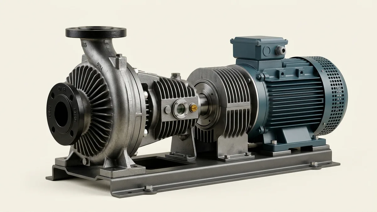
Hot Oil Pump Piping & Expansion Tank Layout Rules: Standards, Sizing Math & Installation Guide
A comprehensive piping engineering design manual, thermal expansion hydraulic standard, and expansion tank configuration guide for process engineers, piping designers, and utility superintendents across Vatva GIDC, Narol, Odhav, Surat, and Gujarat.
Quick Answer
In the high-temperature chemical synthesis complexes, continuous textile stenter finishing plants, resin compounding reactors, and multi-daylight laminate pressing facilities of Gujarat—spanning Ahmedabad (Vatva GIDC, Narol, Odhav), Surat, Ankleshwar, and Dahej—thermic fluid pumps circulate organic heat transfer media at bulk temperatures between 250°C and 320°C. While selecting a heavy-duty pump conforming to DIN 24255 is essential, over 60% of premature seal failures, hydraulic cavitation erosion, and casing flange cracking originate directly from incorrect suction piping layout, undersized expansion tank piping, or uncompensated piping thermal stress. Thermal fluid piping systems expand axially by over 3.5 mm per meter between ambient startup and 300°C. If suction and discharge pipe headers lack flexible expansion U-loops, massive thermal growth forces (often exceeding 15,000 N) transfer directly into the pump nozzles, twisting casing alignment and destroying mechanical seal faces within days. In operating installations, placing the expansion tank at insufficient elevation (< 3.5 m) starves the pump of Net Positive Suction Head Available (NPSHa), causing chronic vapor flash cavitation. Designing an industrial hot oil circulation loop requires strict mathematical sizing, deaerator degassing branches, and cold seal loop barriers conforming to ISO 5199, ISO 2858, and DIN 24255 standards.
Key Takeaways
- Maintain Minimum Expansion Tank Elevation (≥ 3.5 m). Position the expansion tank 3.5 to 5.0 meters above the pump suction centerline to provide positive static head (Z_static) and prevent cavitation.
- Install Top-Flat Eccentric Reducers. Never install concentric reducers on horizontal suction piping; top-flat reducers eliminate high-point vapor pocket accumulation.
- Incorporate Flexible Thermal Expansion U-Loops. Thermal piping growth must be absorbed by directional expansion loops to keep nozzle forces well below allowable limits.
- Isolate Expansion Tank with Cold Seal Loop. Maintain expansion tank oil temperature below 70°C using a non-insulated seal leg to prevent oxidative oil degradation.
Introduction
Across Gujarat's industrial centers—including the chemical intermediate plants of Vatva GIDC, Odhav, and Ankleshwar, the massive textile stenter belts of Narol and Surat, and the petrochemical terminals of Dahej—thermic fluid pumps circulate synthetic and mineral heat transfer media at bulk temperatures between 250°C and 320°C.
Piping design for high-temperature thermal oil systems differs radically from standard water or chemical transfer loops:
- The Extreme Thermal Expansion: Carbon steel piping expands linearly by 3.5 mm per meter between ambient (25°C) and operating heat (300°C). Without flexible expansion loops, unconstrained thermal growth exerts tons of thrust directly onto pump suction and discharge nozzles.
- The Net Positive Suction Head Challenge: At 300°C, thermal cracking light-ends elevate fluid vapor pressure. Maintaining adequate NPSHa requires elevated expansion tank positioning (> 3.5 m) and smooth suction line geometry.
- The Oxidation Hazard: Hot thermal fluid reacts violently with atmospheric oxygen above 70°C, forming sludge and acidic varnishes. Expansion tanks must remain cool (< 70°C) via a dedicated cold seal barrier loop.
- The Engineering Standard: Following ISO 5199, ISO 2858, and DIN 24255 standards—incorporating expansion U-loops, top-flat eccentric reducers, and properly sized expansion branches—guarantees maximum machinery uptime.
2. Master Thermal Oil Piping & Expansion Tank Design Matrix
Review the standard piping engineering specifications, velocity limits, and expansion tank parameters for high-temperature service:
| Piping System Component | Engineering Standard / Rule | Recommended Sizing / Metric | Operating Function |
|---|---|---|---|
| Suction Piping Velocity | ISO 5199 / HI 14.6 | 1.0 to 1.8 m/s | Minimizes suction friction losses (h_f); prevents cavitation |
| Discharge Piping Velocity | ISO 5199 | 2.0 to 3.0 m/s | Optimizes pressure drop vs piping capital cost |
| Expansion Tank Elevation | ISO 5199 / DIN 24255 | ≥ 3.5 to 5.0 meters above pump | Provides static head (Z_static) for positive NPSHa |
| Expansion Line Diameter | Thermal Sizing Formula | D_exp = 15 + 1.4 · √(V_sys) mm | Accommodates thermal fluid expansion volume without surge |
| Cold Seal Leg Temperature | Thermal Barrier Rule | < 70°C at expansion tank | Prevents atmospheric oxidation and fluid degradation |
3. The Hydraulic Physics, Fluid Expansion Math & Sizing Equations
Net Positive Suction Head Available Equation (NPSHa = [P_exp - P_v] / [ρ· g] + Z - h_f)
Available Net Positive Suction Head at the pump suction nozzle is calculated as:
Interactive Engineering Hydraulic Sizer
Live ISO 5199 / API 610 Dynamic EngineWhere:
- P_exp is expansion tank pressure (101.3 kPa for atmospheric vented tanks).
- P_v is fluid vapor pressure at operating temperature.
- ρ_fluid ≈ 690 kg/m³ (hot oil at 300°C).
- Z_static is vertical height of expansion tank liquid level above pump centerline.
- h_f,suction is total friction head loss across suction piping, valves, and strainer.
- To maintain an engineering safety margin of NPSHa ≥ NPSHr + 1.5 m, the expansion tank liquid level must strictly be elevated Z_static ≥ 3.5 to 5.0 meters above pump suction centerline.
Thermal Fluid Volumetric Expansion Math (V_expansion = V_total · β· ΔT)
As thermal fluid heats from ambient (25°C) to 300°C, it undergoes volumetric thermal expansion:
Where:
- β_fluid ≈ 0.00085 /°C (volumetric thermal expansion coefficient).
- ΔT = 300°C - 25°C = 275°C.
- Net Expansion Fraction:
- For a 10,000 Liter thermal fluid plant inventory, expanded fluid volume is 2,340 Liters.
- The expansion tank total capacity must equal 1.3× to 1.5× the expanded volume (3,000 to 3,500 Liters) to maintain safe operating levels.
Expansion Pipe Sizing Formula (d_pipe = 15 + 1.4 · √(V_sys))
Under ISO 5199 and DIN 24255 thermal installation guidelines, minimum expansion line inner diameter is calculated as:
- For a 10,000 Liter system (V_sys = 10 m³):
- Installing an undersized expansion pipe (e.g., DN50 / 2-inch) restricts fluid return during thermal surges, over-pressuring the heater loop.
Piping Linear Thermal Growth Equation (ΔL = α_steel · L · ΔT)
Linear expansion of carbon steel piping under operating heat is calculated as:
Where:
- α_steel ≈ 13.0 × 10^-6 m/m·°C (for ASTM A106 carbon steel).
- For a 20 meter pipe header operating at 300°C (T_amb = 25°C):
- Rigid piping without flexible U-loops transfers this entire displacement directly into pump nozzles, cracking flanges and distorting bearings.
Allowable Pump Nozzle Moment & Force Limits (F_nozzle ≤ F_ISO 5199)
ISO 5199 and API 610 strictly specify maximum allowable forces (F_x, F_y, F_z) and moments (M_x, M_y, M_z) on pump flanges. Incorporating 3D piping loops ensures nozzle forces remain < 30% of maximum allowable limits.
4. The 5 Critical Piping Layout Mistakes Causing Pump Failure
Mistake 1: Low Expansion Tank Elevation Causing Flashing Cavitation
- Mechanism: Placing expansion tank on intermediate mezzanine only 1.0 to 1.5 meters above pump.
- Symptoms: Pump rattles like gravel at 280°C; discharge pressure swings; impeller vanes suffer cavitation erosion.
- Fix: Relocate expansion tank to roof structure or high gantry ≥ 3.5 to 5.0 meters above pump suction nozzle.
Mistake 2: Concentric Reducers Trapping High-Point Vapor Pockets
- Mechanism: Installing symmetrical concentric reducers on horizontal pump suction lines.
- Symptoms: Vapor bubbles collect at top slope; large gas slugs enter impeller eye, causing hydraulic surging and seal dry-run.
- Fix: Install top-flat eccentric reducers with flat edge on top to allow continuous upward vapor migration.
Mistake 3: Rigid Suction Piping Imposing Massive Nozzle Strain
- Mechanism: Straight, unanchored pipe run connecting heater outlet directly to pump suction without expansion loops.
- Symptoms: Pump casing twists under heat; coupling misalignment jumps to > 1.20 mm; mechanical seal leaks; bearings overheat.
- Fix: Fabricate directional expansion U-loops and install sliding spring hangers adjacent to pump skid.
Mistake 4: Missing or Improperly Piped Deaerator Degassing Branch
- Mechanism: Boiling out new oil charge without a dedicated deaerator degassing vessel.
- Symptoms: Trapped moisture and volatile cracking gases cannot vent; pump surges violently during initial heat-up.
- Fix: Install a vertical deaerator pot at the highest point before pump suction with a dedicated degassing vent line to expansion tank.
Mistake 5: Hot Oil Circulation Entering Open Expansion Tank
- Mechanism: Connecting main process return into expansion tank instead of maintaining a dead-leg cold seal loop.
- Symptoms: Expansion tank temperature reaches > 180°C; rapid fluid oxidation into black sludge and acidic varnish.
- Fix: Ensure expansion line connects to pump suction header as a static expansion leg; isolate tank from continuous flow.
5. Step-by-Step Thermal Piping Erection & Commissioning SOPs
Execute this structured engineering protocol when installing or retrofitting thermal fluid pump piping systems:
Phase 1: Piping Routing, Slope & Anchor Support Design SOP
- Suction Header Routing: Route suction pipe with continuous upward slope (> 1:100) toward deaerator vessel.
- Independent Pipe Supports: Support all piping independently using heavy base stands and sliding spring hangers. Ensure zero pipe weight rests on pump nozzles.
Phase 2: Expansion Tank & Cold Seal Loop Erection SOP
- Elevation Positioning: Erect expansion tank liquid level at ≥ 3.5 to 5.0 meters above pump centerline.
- Cold Seal Leg Piping: Install uninsulated vertical expansion line (> 4 meters length); verify expansion tank temperature remains < 70°C.
Phase 3: Deaerator Vessel & Bypass Lineup SOP
- Deaerator Pot Installation: Install vertical deaerator vessel in main pump suction stream.
- Degassing Lineup: Connect top degassing vent line with throttling valve directly into expansion tank vapor space.
Phase 4: Cold Flange Alignment & Zero-Strain Verification SOP
- Flange Bolt Test: With pump anchored and piping fully hung, loosen all suction and discharge flange bolts.
- Zero Strain Check: Flange faces must remain parallel within < 0.15 mm and bolt holes must align without prying bars.
Phase 5: Dynamic Rotor Balancing to ISO 5199 Grade G2.5 SOP
- Dynamic Balancing: Dynamically balance assembled impeller, shaft, and keys on dynamic balancing machine.
- Balance Certification: Achieve residual unbalance < 1.0 g\cdotmm/kg conforming to ISO 5199 Grade G2.5.
Phase 6: Thermal Growth Laser Alignment & Hot Commissioning SOP
- Cold Pre-Offset: Set electric motor shaft -0.45 mm lower than pump shaft using 316L precision shims.
- Hot Laser Verification: Bring loop to 280°C; verify running concentricity ≤ 0.03 mm and vibration < 1.80 mm/s RMS (Zone A).
6. Materials of Construction, Metallurgy & Piping Specifications
Nodular Ductile Iron (GGG 40.3) & Cast Carbon Steel (ASTM A216 WCB)
- Pressure Containment: High-temperature Nodular Ductile Iron (EN-GJS-400-18-LT / GGG 40.3) or Cast Carbon Steel (ASTM A216 WCB) casings capable of withstanding thermal shock and 16 bar working pressure up to 350°C.
Heavy-Wall Carbon Steel Piping (ASTM A106 Grade B, Schedule 40)
- Piping Lines: ASTM A106 Grade B heavy-wall carbon steel piping with butt-welded fittings conforming to ASME B16.9 and Class 150 / 300 flanges conforming to ASME B16.5.
Flexible Spiral-Wound Grafoil Gaskets (Class 150 / 300)
- Flange Gaskets: 316L stainless steel spiral-wound gaskets with flexible expanded graphite (Grafoil) filler, capable of withstanding 350°C thermal cycling without relaxation.
Monolithic Direct-Sintered Silicon Carbide (SSiC) Seal Faces
- Mechanical Seal Faces: Solid direct-sintered silicon carbide (SSiC) running against SSiC or Tungsten Carbide faces with flexible Grafoil secondary packings.
7. The Process Engineer's Piping Layout Decision Matrix
Follow this structured engineering guide when reviewing thermal oil piping and tank layouts:
| Identified Piping Defect | Dominant System Symptom | Confirmed Root Cause | Mandatory Corrective Engineering Action |
|---|---|---|---|
| Low static head (< 2.0 m) | Cavitation noise at 280°C | Inadequate expansion tank elevation | Elevate tank to ≥ 3.5 to 5.0 meters |
| Flange bolts bound in holes | High 2X vibration; seal failure | Piping thermal expansion strain | Fabricate directional expansion U-loops |
| Concentric suction reducer | Intermittent flow surging / drops | Top-pipe vapor pocket accumulation | Replace with top-flat eccentric reducer |
| Expansion tank > 140°C | Oil darkening, sludge formation | Continuous flow through expansion tank | Reconfigure as static dead-leg cold seal loop |
| Violent boiling during startup | Pressure swings at 105°C | Moisture trapped in circulation loop | Execute thermal boil-out via deaerator vent |
8. Worked Gujarat Textile, Chemical & Processing Mill Case Studies
Case 1: Vatva GIDC Chemical Synthesis Reactor Hot Oil Pump Piping Overhaul
- Plant Context: An azo dye synthesis facility in Vatva GIDC operating a 120 m³/h thermic fluid circulation loop at 300°C.
- Problem: Mechanical seals failed every 4 to 6 weeks; pump casing flanges cracked twice; motor ran hot.
- Root Cause: Suction header ran straight for 18 meters without expansion loops. At 300°C, +62 mm of thermal expansion exerted over 18,000 N of thrust onto the pump suction nozzle, distorting the casing.
- Action Plan: Teflow Pumps engineering team:
- Re-engineered piping layout with dual directional expansion U-loops. - Installed top-flat eccentric reducers and spring-loaded pipe supports. - Dynamically balanced impeller to ISO 5199 Grade G2.5 and laser aligned pump skid with -0.46 mm cold target offset.
- Outcome: Flange nozzle strain reduced to < 800 N; vibration dropped to 0.78 mm/s RMS (Zone A); zero seal failures over 26 consecutive operating months.
Case 2: Narol Continuous Cotton Stenter Hot Oil Piping and Expansion Loop Fix
- Plant Context: A textile processing mill in Narol operating dual 80 m³/h hot oil pumps (285°C).
- Problem: Severe cavitation noise and flow loss at peak stenter drying load.
- Root Cause: Expansion tank was mounted on a mezzanine only 1.2 meters above the pump suction, starving NPSHa.
- Action Plan: Elevated expansion tank to roof truss gantry (+4.8 meters static head).
- Outcome: Suction pressure increased by +0.32 bar; cavitation noise completely eliminated.
Case 3: Surat Synthetic Weaving Thermic Fluid Pump Expansion Tank Recovery
- Plant Context: A polyester yarn processing plant in Surat operating a 60 m³/h circulation loop (270°C).
- Problem: Thermal fluid oxidized rapidly, turning into thick black sludge after only 6 months of operation.
- Root Cause: Main return line passed directly through the expansion tank, maintaining tank oil at 190°C open to atmosphere.
- Action Plan: Re-piped expansion tank as a static dead-leg cold seal loop (4 meters uninsulated leg).
- Outcome: Expansion tank oil temperature dropped to 54°C; fluid oxidation completely arrested.
Case 4: Odhav Industrial Estate Multi-Daylight Press Piping Reconfiguration
- Plant Context: A decorative laminate pressing facility in Odhav operating hot oil platens at 240°C.
- Problem: Symmetrical concentric reducers on suction line trapped vapor pockets, causing hydraulic surges.
- Action Plan: Replaced concentric reducers with top-flat eccentric reducers.
- Outcome: Hydraulic surging eliminated; platen temperature uniformity improved within ± 1.5°C.
Case 5: Ankleshwar GIDC Specialty Chemical Reactor Thermal Loop Overhaul
- Plant Context: A pharma intermediate manufacturing plant in Ankleshwar GIDC operating at 315°C.
- Problem: Moisture boil-out caused violent heater tripping during commissioning.
- Action Plan: Installed a dedicated vertical deaerator degassing vessel with metered vent to expansion tank.
- Outcome: Stripped all trace moisture smoothly during initial 105°C-120°C degassing cycle.
Case 6: Dahej PCPIR Petrochemical Terminal Heat Transfer Circulation Audit
- Plant Context: A petrochemical terminal in Dahej PCPIR operating high-flow BB1 split-case hot oil pumps (2500 m³/h).
- Problem: Thermal growth of heavy DN300 headers created excessive nozzle moment loads on pump casing.
- Action Plan: Installed multi-plane expansion loops and calibrated constant-effort spring supports.
- Outcome: Reduced nozzle moment to within 20% of ISO 5199 allowable limits.
9. Comprehensive Master Thermal Oil Piping Installation Checklist
Execute this piping and expansion tank verification protocol before commissioning hot oil circulation pumps:
Thermal Oil Pump Piping & Expansion Tank Commissioning Protocol
10. Summary & Specialized Piping Engineering Services in Gujarat & India
Optimizing thermal oil pump piping and expansion tank layouts—elevating expansion tanks ≥ 3.5 to 5.0 meters, installing top-flat eccentric reducers, fabricating flexible thermal expansion U-loops, isolating expansion tanks with cold seal loops, and dynamically balancing rotating assemblies to ISO 5199 Grade G2.5 across Vatva GIDC, Narol, Odhav, Surat, Ankleshwar, and Dahej—conforming to ISO 5199, ISO 2858, and DIN 24255 standards—is the proven engineering standard for maximum reliability.
Partnering directly with an established Gujarat rotating machinery manufacturer provides chemical plant piping engineers, textile mill managers, and utility superintendents with immediate technical access to on-site piping stress analysis teams, precision laser alignment tools, dynamic balancing facilities, and genuine spares dispatched directly from our Ahmedabad factory. Our technical engineers provide emergency on-site troubleshooting, turnkey pump overhauls, and complete thermal loop audits.
Teflow Pumps operates a specialized industrial machinery manufacturing and service facility in Ahmedabad, providing emergency thermic fluid pump overhauls, piping layout engineering audits, precision laser hot alignment, dynamic balancing, custom impeller casting, and genuine rotating equipment spares across Gujarat and India conforming to ISO 5199, ISO 2858, DIN 24255, and IS 5120 standards.
- Direct Technical & Emergency Helpline: +91 98251 62709
- WhatsApp Technical Desk: Share piping isometric drawings, expansion tank elevation photos, pump nameplate photos, operating temperatures (°C), or vibration spectra to wa.me/919825162709 for immediate technical review, piping layout calculation, and formal quotation.
- Request an On-Site Piping Audit & Pump Overhaul: Contact our senior rotating equipment engineers for emergency plant surveys, hot alignment proposals, and formal quotation. Our engineering team conducts comprehensive thermal evaluations, verifies ISO 5199 criteria, provides precision on-site or workshop reconditioning, and dynamically balances overhauled hot oil pumps to ensure maximum uptime across Gujarat's textile and chemical processing mills. We provide rapid technical evaluations, on-site plant surveys, and formal quotes.