
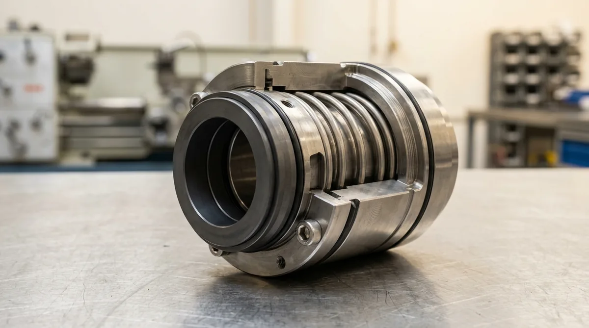
Slurry & Dewatering Pump Mechanical Seals: Engineering Abrasion-Proof Solutions for Heavy Industrial Duties
A definitive technical engineering guide, heavy slurry seal selection manual, and dewatering reliability protocol for maintenance engineers, ETP plant managers, and rotating equipment specialists across Ahmedabad, Naroda GIDC, Vatva GIDC, Ankleshwar, Morbi, and Gujarat.
Quick Answer
In industrial wastewater effluent treatment plants (ETPs), Common Effluent Treatment Plants (CETPs), ceramic tile body-slip preparation units, mining quarry sumps, and chemical crystallization reactors across Gujarat—such as in Naroda GIDC, Vatva GIDC, Ankleshwar, Panoli, Dahej PCPIR, and Morbi—centrifugal slurry and dewatering pumps handle high concentrations of sharp, abrasive mineral solids (15% - 65% solids by weight) including silica sand (1100 HV), titanium dioxide, calcium sulfate gypsum, iron oxide scales, and fly ash. When industrial plants install general-purpose mechanical seals featuring soft resin-impregnated Carbon faces, small multi-coil internal springs, and narrow cylindrical stuffing boxes, the seal fails within 48 to 120 operating hours. Abrasive solids pack tightly between the multi-spring coils ("spring hang-up"), dynamic secondary O-rings are pinned by abrasive silt, and sharp particles enter the microscopic sealing interface (0.5 µm), cutting deep radial gouges that dump slurry into the bearing housing. Conforming to ISO 5199, ISO 2858, IS 5120, and API 682 standards, achieving multi-year operational reliability on abrasive slurry duties requires hard-on-hard seal face pairings (Monolithic Silicon Carbide SSiC vs Nickel-Bound Tungsten Carbide Ni-TC), isolated or open external wave springs, large-tapered self-flushing seal chambers, and engineered auxiliary piping plans (API Plan 31 cyclone separators or Plan 32 clean flush injection).
Key Takeaways
- Never Use Carbon-Faced or Multi-Spring Mechanical Seals in Slurry Duties. Abrasive solids pack internal springs and gouge soft carbon noses within days.
- Pair Monolithic Silicon Carbide (SSiC) with Nickel-Bound Tungsten Carbide (Ni-TC). Hard-on-hard pairings resist 3-body abrasive particle rolling and thermal shock.
- Deploy Large-Bore Tapered Seal Chambers (Vortex Clearing). Tapered housings use centrifugal force to fling heavy solids away from the seal faces.
- Isolate Dynamic Springs Outside the Abrasive Process Fluid Zone. External wave springs or rubber bellows eliminate spring clogging and dynamic hang-up.
Introduction
In continuous effluent treatment facilities, Common Effluent Treatment Plants (CETPs), ceramic tile manufacturing plants, chemical pigment synthesis units, and industrial dewatering sumps across Ahmedabad, Naroda GIDC, Vatva GIDC, Ankleshwar, and Morbi, centrifugal pumps operate under extreme tribological duress.
ETP superintendents, plant maintenance managers, and rotating machinery engineers confront severe recurring dilemmas:
- The Rapid Seal Failure Cycle in Slurry Sumps: Standard industrial mechanical seals fail every 7 to 20 days when exposed to abrasive slurry, sludge, or ceramic slip, leaking toxic chemicals into pump sumps and flooding motor frames.
- The Abrasive Fluid Film Mechanism: Mechanical seal faces rely on a microscopic fluid film (0.5 µm). In slurry duties, suspended solid particles larger than this fluid film enter the sealing gap, acting as an abrasive cutting compound that grinds away lapped faces and jams mechanical springs.
- The Engineering Standard: Implementing a heavy-duty slurry sealing standard conforming to ISO 5199, ISO 2858, IS 5120, and API 682 standards—mandating monolithic Silicon Carbide or Nickel-Bound Tungsten Carbide hard-on-hard faces, isolated single wave springs, large tapered seal chambers, and API Plan 31/32 piping—eliminates spring clogging, prevents face scoring, and extends slurry pump MTBF beyond 25,000 operating hours.
2. Master Slurry & Dewatering Pump Mechanical Seal Comparison Matrix
Compare mechanical seal configurations across slurry concentration and particle abrasiveness levels:
| Slurry Severity Class | Solids Content (% wt) & Hardness | Recommended Seal Architecture | Face Pairing & Metallurgy | Auxiliary Piping Plan |
|---|---|---|---|---|
| Mild Slurry / ETP Dewatering | 5 - 15% Solids (< 500 HV) | Single Cartridge / Wave Spring | Monolithic SSiC vs FDA Carbon | API Plan 11 with Bushing |
| Moderate Slurry / Pigment ETP | 15 - 30% Solids (500 - 900 HV) | Heavy-Duty Single Slurry Seal | Direct-Sintered SSiC vs SSiC | API Plan 31 (Cyclone) |
| Severe Abrasive Slurry / Sand | 30 - 50% Solids (> 1000 HV) | External Slurry Cartridge | Ni-Bound Tungsten Carbide vs SSiC | API Plan 32 (Clean Flush) |
| Ceramic Slip / Heavy Sludge | 50 - 65% Solids (> 1200 HV) | Dual Pressurized Slurry Seal | Ni-Bound Tungsten Carbide vs Ni-TC | API Plan 53A / 54 Barrier |
| Corrosive Acid Slurry (ETP) | 10 - 35% Solids (pH 0.5 - 3) | Non-Metallic PTFE Bellows Seal | Direct-Sintered SSiC vs SSiC | API Plan 32 External Flush |
3. The Tribological Physics & Solid Particle Fluid Mechanics of Slurry Abrasion
Solid Particle Erosion Mechanics (2-Body Gouging vs 3-Body Rolling Abrasion)
Mechanical wear on seal faces operating in slurry environments occurs through two distinct tribological mechanisms:
Interactive Durand Slurry Settling Velocity Sizer
Live ISO 5199 / API 610 Dynamic Engine- 2-Body Gouging Wear (R_wear > 1.2): When hard mineral particles (e.g., quartz sand, 1100 HV) become embedded in a soft seal face (e.g., carbon, 90 HV), the protruding particle acts as a fixed cutting tool, micro-machining deep radial tracks into the opposing rotating ring.
- 3-Body Rolling Wear (0.8 ≤ R_wear ≤ 1.2): When both faces are hard (e.g., SSiC, 2800 HV), loose solid particles roll between the sliding faces, fracturing at their sharp asperities and polishing the lapped mirror with minimal material loss.
Particle Size Distribution (d_50) vs Microscopic Seal Fluid Film (h_0 ≈ 0.5 µm)
- Fluid Film Hydrodynamics: Under steady-state hydrodynamic rotation, mechanical seal faces are separated by a lubricating fluid film of thickness h_0 ≈ 0.3 - 0.8 µm.
- Particle Ingress Threshold: Slurry particles with diameter d > 2.0 µm are mechanically excluded from entering the interface by hydrodynamic pressure gradients at the outer face diameter (OD). However, sub-micron fines (d < 1.0 µm) can enter the film, causing localized fluid film boiling, boundary lubrication, and micro-frictional thermal spikes (> 200°C). Utilizing hard-on-hard pairings prevents these trapped micro-fines from embedding into the seal matrix.
Centrifugal Vortex Hydrodynamics & Solids Expulsion in Tapered Chambers
In conventional narrow cylindrical stuffing boxes, solid particles migrate toward the seal faces due to low fluid velocity:
- Tapered Bore Chamber Advantage: A large 45^° tapered bore seal chamber utilizes the high rotational velocity imparted by the pump shaft and seal collar. Heavy solid particles are centrifuged radially outward toward the large diameter of the taper and continuously swept backward into the pump volute casing, maintaining a clean, solids-free fluid zone immediately surrounding the mechanical seal faces.
Slurry Particle Packing & Spring Hang-Up Kinetics
- Spring Compaction Mechanism: In standard multi-spring seals, fluid stagnates inside the spring pockets. Fine sludge, flocculants, and sand particles settle between the small spring coils (2 - 3 mm coil spacing). Within days, dehydrated slurry packs into a solid block, preventing the spring from expanding to compensate for normal face wear. The seal loses dynamic closing pressure, resulting in catastrophic slurry leakage.
4. The 4 Critical Slurry Pump Mechanical Seal Failure Modes in Gujarat Industrial Units
Failure Mode 1: Multi-Coil Spring Silt Compaction & Loss of Closing Force
- Failure Mechanism: Pumping abrasive ETP sludge or chemical effluent with internal multi-coil springs leads to rapid mud packing. The springs lock solid, preventing dynamic tracking of shaft runout.
- Engineering Solution: Standardize on external isolated single wave springs or large conical single springs positioned completely outside the slurry fluid zone.
Failure Mode 2: Dynamic O-Ring Pitting & Shaft Sleeve Erosion
- Failure Mechanism: Abrasive particles lodge beneath dynamic secondary O-rings. As the shaft oscillates axially, trapped sand acts as sandpaper, cutting deep fretting grooves into stainless steel shaft sleeves.
- Engineering Solution: Convert to elastomeric rubber bellows seals with static shaft gripping, eliminating all sliding dynamic O-rings along the sleeve.
Failure Mode 3: 3-Body Abrasive Scoring of Ceramic Lapped Faces
- Failure Mechanism: Installing soft carbon faces in slurry duties allows quartz sand to embed into the carbon, grooving both rings and destroying optical flatness.
- Engineering Solution: Upgrade to hard-on-hard direct-sintered monolithic Silicon Carbide (SSiC) vs Nickel-Bound Tungsten Carbide (Ni-TC).
Failure Mode 4: Thermal Shock Face Shattering from Slurry Cavitation
- Failure Mechanism: When slurry pumps cavitate due to high solids viscosity or low suction head, seal faces run dry and overheat (> 250°C). Re-entering cold slurry causes sudden thermal shock, fracturing brittle ceramic rings.
- Engineering Solution: Install Nickel-Bound Tungsten Carbide rotating rings offering superior fracture toughness (K_1c > 10 MPa\cdotm^1/2) compared to standard ceramics.
5. Sanitary Materials of Construction & Cleanroom Standards
Direct-Sintered Monolithic SSiC vs Porous Silicon Carbide
- Silicon Carbide Metallurgy: Monolithic alpha direct-sintered Silicon Carbide (2800 HV, 99.5% SiC) with zero free silicon binders, diamond-lapped to ≤ 1 helium light band (0.3 µm) for universal resistance across 0 - 14 pH and extreme resistance against abrasive slurry scratching. The high thermal conductivity (120 W/m\cdotK) rapidly dissipates boundary frictional heat.
Nickel-Bound (94% WC - 6% Ni) vs Cobalt-Bound Tungsten Carbide
- Tungsten Carbide Metallurgy: Premium vacuum-sintered Nickel-Bound Tungsten Carbide (94% WC - 6% Ni, 1500 HV) providing exceptional fracture toughness, mechanical shock resistance, and corrosion resistance in chemical effluents (avoiding cobalt leaching in acidic duties).
Hastelloy C-276 & Heavy-Section Single Wave Springs
- Heavy-Section Springs: Large cross-section single wave springs manufactured from Hastelloy C-276 (UNS N10276) or SS316, positioned outside the product chamber to provide clog-free closing force without sludge accumulation.
Heavy-Duty Rubber Bellows & Elastomeric Diaphragms
- Rubber Bellows Design: Heavy-duty molded Nitrile (NBR), EPDM, or Fluoroelastomer (FKM) elastomeric bellows that grip the shaft sleeve statically, completely eliminating dynamic O-ring fretting and spring clogging in dewatering and wastewater duties.
6. Step-by-Step Slurry Mechanical Seal Selection & Piping Plan SOPs
Execute these structured engineering SOPs when specifying and installing slurry pump seals:
Phase 1: Slurry Rheology & Particle Hardness Profiling SOP
- Slurry Characterization: Measure solids concentration (% wt), specific gravity (SG), dynamic viscosity (µ), particle size distribution (d_50, d_90), and Mohs hardness.
- Chemistry Audit: Determine fluid pH (0 - 14), chloride content (ppm Cl^-), operating temperature (°C), and potential for chemical crystallization.
Phase 2: Hard-on-Hard Seal Face Metallurgy Selection SOP
- Face Pairing Rules:
- For pH 4 - 14 and heavy abrasive slurry: Select Direct-Sintered SSiC vs Nickel-Bound Tungsten Carbide. - For pH < 4 (hot acidic slurry): Select Direct-Sintered SSiC vs Direct-Sintered SSiC. - For dewatering sumps with intermittent dry running: Select Nickel-Bound Tungsten Carbide vs Nickel-Bound Tungsten Carbide.
Phase 3: Tapered Seal Chamber & Vortex Expeller Integration SOP
- Housing Geometry: Replace narrow cylindrical stuffing boxes with large 45^° tapered bore seal chambers or install vortex-clearing throat bushings (SpiralTrac style) to expel solids continuously.
- Radial Clearance: Maintain minimum 12 mm radial clearance between seal rotating outer diameter and chamber wall.
Phase 4: API Auxiliary Piping Plan Selection (Plan 31 vs Plan 32 vs Plan 54) SOP
- Plan Selection:
- API Plan 31 (Cyclone Separator): Use for moderate slurries (< 15% solids) with particles having specific gravity > 2.0. - API Plan 32 (Clean External Flush): Use for heavy slurries (> 20% solids) where process dilution is acceptable (+1.5 bar over stuffing box pressure). - API Plan 54 (Pressurized Dual Seal Loop): Use for zero-dilution toxic or hazardous slurry pumping.
Phase 5: Seal Chamber Pressure Balancing & Dynamic Setting SOP
- Setting Axial Pre-load: Set cartridge seal drive collar to exact factory datum line. Confirm spring working length provides optimal face contact pressure (0.25 - 0.45 MPa) to resist slurry hydraulic separation.
Phase 6: Slurry Hydrotest & Controlled Commissioning Run-In SOP
- Priming & Hydrotest: Pressurize pump casing with water to 1.5× operating pressure (6.0 bar); confirm zero weeping. Flood seal chamber completely before energizing motor to prevent dry-running fracture.
7. Worked Gujarat Slurry & Dewatering Industrial Case Studies
Case 1: Naroda GIDC CETP Sludge Dewatering Pump Mechanical Seal Upgrade
- Plant Context: Common Effluent Treatment Plant in Naroda GIDC operating six heavy sludge dewatering pumps (35% solids, pH 6.8).
- Problem: Multi-spring component seals failed every 10 to 14 days; teardown showed spring pockets packed solid with biological sludge and quartz sand.
- Action Plan: Converted all dewatering pumps to heavy-duty rubber bellows cartridge seals with monolithic SSiC vs Nickel-Bound Tungsten Carbide hard faces and open single wave springs.
- Outcome: Spring clogging eliminated 100%; mechanical seal operating life extended from 2 weeks to over 22 consecutive operating months; saved Rs 8,50,000 in annual maintenance costs.
Case 2: Morbi Ceramic Cluster Glaze & Ball Mill Slip Transfer Pump Fix
- Plant Context: A ceramic tile manufacturing facility in Morbi pumping viscous ceramic glaze and ball mill body slip (60% solids, 1200 HV).
- Problem: Mechanical seals leaked abrasive glaze into bearing brackets every 3 weeks, destroying shaft sleeves and bearings.
- Action Plan: Retrofitted pumps with large 45^° tapered bore seal chambers and balanced external slurry cartridge seals with Tungsten Carbide faces.
- Outcome: Glaze solids centrifugally expelled from faces; seal life extended to 24 consecutive operating months.
Case 3: Vatva GIDC Chemical Effluent Neutralization Slurry Pump Overhaul
- Plant Context: A specialty chemical plant in Vatva GIDC pumping acidic gypsum neutralization slurry (25% solids, pH 2.5, 65°C).
- Problem: Cobalt-bound Tungsten Carbide faces suffered chemical leaching, while carbon faces grooved within 20 days.
- Action Plan: Standardized on 100% direct-sintered monolithic SSiC vs SSiC faces with Hastelloy C-276 hardware and API Plan 32 clean water flush.
- Outcome: Chemical leaching and abrasive scoring eliminated completely; continuous operation across 26 consecutive operating months.
Case 4: Dahej PCPIR Coal Handling & Ash Slurry Dewatering Seal Retrofit
- Plant Context: A coal-fired power and chemical utility in Dahej PCPIR pumping abrasive coal dust and fly ash sump dewatering slurry.
- Problem: Submersible dewatering pump seals failed within 1 month due to dynamic O-ring fretting and sand grooving.
- Action Plan: Installed heavy-duty oil-lubricated dual cartridge seals with solid Nickel-Bound Tungsten Carbide faces on both inboard and outboard positions.
- Outcome: Zero slurry ingress into motor chamber; continuous service over 28 consecutive operating months.
Case 5: Ankleshwar GIDC Pigment Filter Press Feed Pump Hard Face Upgrade
- Plant Context: A phthalocyanine pigment manufacturing unit in Ankleshwar GIDC operating high-pressure filter press feed pumps (8.0 bar, 40% solids).
- Problem: High pressure blew abrasive pigment slurry between seal faces during cycle shutoff spikes.
- Action Plan: Retrofitted pumps with balanced heavy-duty single slurry seals with hydraulic pressure balancing (k_balance = 0.75) and direct-sintered SSiC faces.
- Outcome: Pressure spike face separation eliminated; seal life extended to 20 consecutive operating months.
Case 6: Surat Dyeing ETP Aeration Tank Transfer Pump Rubber Bellows Conversion
- Plant Context: A textile dyeing mill in Surat transferring fibrous effluent with suspended sand and lint.
- Problem: Fibrous lint wrapped around dynamic multi-coil springs, causing spring hang-up and daily weeping.
- Action Plan: Converted pumps to elastomeric rubber bellows slurry seals with zero exposed springs in the product zone.
- Outcome: Lint entanglement eliminated 100%; continuous maintenance-free operation over 24 consecutive operating months.
8. Step-by-Step Slurry Mechanical Seal Troubleshooting Flowchart
Follow this structured engineering guide and material selection protocol when troubleshooting abrasive slurry and dewatering pump mechanical seal failures:
| Slurry Seal Physical Failure Symptom | Diagnostic Root Cause Issue | Immediate Corrective Maintenance Action |
|---|---|---|
| Springs Packed with Solid Mud / Sand | Internal Multi-Spring Design in Slurry | Convert to external wave spring / rubber bellows |
| Deep Radial Grooves on Lapped Faces | Soft Carbon Used in Abrasive Slurry | Upgrade to Monolithic SSiC vs Tungsten Carbide |
| Deep Grooves Cut into Shaft Sleeve | Abrasive Silt Under Dynamic O-Ring | Switch to static elastomeric rubber bellows seal |
| Silicon Carbide Ring Shattered in Pieces | Thermal Shock from Slurry Cavitation | Upgrade to tough Nickel-Bound Tungsten Carbide |
| Slurry Packed Solid in Stuffing Box | Narrow Cylindrical Stuffing Box | Install 45^° tapered bore seal chamber |
| Continuous Slurry Weeping from Gland | Loss of Spring Closing Pre-load | Reset cartridge axial pre-load; clean flush line |
9. Comprehensive Master Slurry Pump Mechanical Seal (FAT) Checklist
Execute this quality verification protocol during slurry pump overhauls and seal commissioning:
Slurry Pump Mechanical Seal Reliability Protocol
10. Summary & Slurry Mechanical Seal Overhaul Services in Gujarat
Eliminating catastrophic spring clogging, preventing abrasive 3-body face scoring, enforcing heavy-duty slurry sealing standards conforming to ISO 5199, ISO 2858, IS 5120, and API 682 standards, and extending slurry pump operating life beyond 25,000 hours across Ahmedabad, Naroda GIDC, Vatva GIDC, Ankleshwar, and Morbi—by utilizing direct-sintered monolithic Silicon Carbide, Nickel-Bound Tungsten Carbide, large tapered seal chambers, and dynamic balancing to Grade G2.5—is the proven engineering standard for modern industrial slurry reliability.
Teflow Pumps operates a specialized rotating machinery overhaul facility in Ahmedabad, providing engineered slurry pump overhauls, abrasion-proof mechanical seal retrofits, tapered seal chamber machining, dynamic balancing, and genuine chemical spares across Gujarat conforming to ISO 5199, ISO 2858, IS 5120, and API 682 standards.
- Direct Technical & Emergency Helpline: +91 98251 62709
- WhatsApp Technical Desk: Share your slurry solids concentration (% wt), fluid chemistry, pump model, or seal failure photos to wa.me/919825162709 for immediate engineering diagnostics, seal selection advice, and formal quotation.
- Request an On-Site Slurry Sealing Audit: Contact our senior reliability engineers for ETP pump surveys, seal chamber retrofits, and formal AMC service quotes.