
Oversized Pump Symptoms: Best Efficiency Point (BEP) Drift, Discharge Recirculation & Corrective Retrofit Engineering Standard
A definitive rotating machinery diagnostic manual, off-BEP failure mode analysis, and pump oversizing correction standard for maintenance engineers, energy managers, and plant utility superintendents across Surat, Sachin, Pandesara, Ahmedabad, and Gujarat.
Quick Answer
Across Gujarat's textile processing complexes (Surat—Sachin, Pandesara), chemical manufacturing zones (Ahmedabad—Vatva, Naroda), and petrochemical facilities (Ankleshwar, Dahej), over 50% of installed centrifugal process and utility pumps are substantially oversized. Plant designers frequently stack multiple compounding safety margins (+15% flow, +20% head, +25% motor power) during project engineering, resulting in pumps that produce far more head and capacity than actual system requirements. To restrict output, plant operators throttle downstream discharge isolation valves by 40% - 70%, forcing the pump to operate far to the left of its Best Efficiency Point (BEP, Q / Q_BEP < 0.60). Operating in this low-flow regime triggers devastating mechanical forces: hydraulic discharge recirculation pits impeller vane tips, massive radial unbalance loads (F_r) cause excessive shaft deflection, seal face flushing collapses leading to thermal heat checking, and bearing temperatures surge past 85°C. Diagnosing oversized pump symptoms and executing engineered corrections conforming to ISO 5199, ISO 2858, IS 5120, and IS 1520 standards—such as precision CNC impeller diameter trimming or VFD speed reduction—permanently eliminates recirculation cavitation, slashes electrical energy waste by 25% - 45%, and extends mean time between failures (MTBF) beyond 40,000 continuous hours.
Key Takeaways
- Recognize the Primary Symptom of Oversizing. A discharge valve throttled > 30% - 50% closed is definitive proof of an oversized pump.
- Operating Far Left of BEP Multiplies Radial Shaft Load (F_r). Radial force scales as F_r = K_r [1 - (Q/Q_BEP)²], deflecting shafts and cracking mechanical seals.
- Discharge Recirculation Inception Occurs Below 65% - 75% BEP. Low-flow vortex shedding causes high-frequency cavitation-like knocking and vane pitting.
- Execute Impeller Trimming to Restore BEP Alignment. Trimming the impeller diameter permanently re-centers pump operation at BEP with 100% open valves.
Introduction
Across Gujarat's vibrant manufacturing landscape—specifically in Surat's synthetic textile weaving clusters (Sachin GIDC, Pandesara), Ahmedabad's chemical manufacturing zones (Vatva, Naroda, Odhav), Ankleshwar GIDC, and Dahej PCPIR—centrifugal process and utility pumps consume substantial electrical energy.
Plant maintenance superintendents, reliability managers, and energy auditors constantly deal with chronic pump issues:
- The Safety Margin Stacking Habit: During plant design, process engineers add a 15% safety factor on flow, piping designers add 20% on head friction, and procurement adds a 25% motor margin. The resulting installed pump is grossly oversized, producing twice the required system head.
- The Operator's Quick Fix: Operators simply turn the discharge handwheel, throttling the valve until process flow matches downstream tank filling rates. However, this throttling forces the pump to operate far to the left of its Best Efficiency Point (BEP), dissipating energy and generating severe destructive hydraulic forces.
- The Engineering Standard: Diagnosing off-BEP operation and implementing engineered retrofits conforming to ISO 5199, ISO 2858, IS 5120, and IS 1520 standards—re-sizing impellers via precision CNC lathe trimming, dynamically balancing rotating assemblies to ISO 5199 Grade G2.5, or installing Variable Frequency Drives (VFDs)—restores hydraulic stability, eliminates seal leaks, and saves lakhs of rupees in electrical power.
2. Master Oversized Pump Diagnostic Symptom Matrix
Review the standard physical symptoms, hydraulic mechanisms, and diagnostic thresholds associated with oversized centrifugal pumps operating off-BEP:
| Diagnostic Parameter | Normal BEP Operation (80% - 110% Q_BEP) | Oversized Pump Operating Left of BEP (< 60% Q_BEP) | Severely Oversized (< 40% Q_BEP) |
|---|---|---|---|
| Discharge Valve Position | 90% - 100% Open | 30% - 50% Throttled | > 60% Throttled / Cracked Open |
| Radial Hydraulic Load (F_r) | Minimal (F_r ≈ 0 - 200 N) | High (F_r ≈ 1,200 - 3,500 N) | Extreme (F_r > 6,000 N, High Deflection) |
| Hydraulic Flow Stability | Smooth, Streamlined Flow | Discharge Recirculation Inception | Severe Suction & Discharge Vortex Cavitation |
| Vibration Level (ISO 5199) | < 1.8 mm/s RMS (Zone A - Good) | 3.5 - 5.5 mm/s RMS (Zone C - Alert) | > 7.0 mm/s RMS (Zone D - Stop) |
| Mechanical Seal Life (MTBF) | > 36 - 48 Months | 3 - 6 Months (Repeat Leaks) | < 30 Days (Face Shattering) |
| Bearing Housing Temperature | 45^° - 55°C | 65^° - 75°C | > 85°C (Lubricant Breakdown) |
| Wasted Electrical Power | < 5% Excess Power | 20% - 35% Power Wasted across Valve | 40% - 60% Power Wasted as Heat |
3. The Hydraulic Physics, Off-BEP Flow Kinematics & Radial Load Math
Operating Left of BEP & The Preferred Operating Region (POR vs AOR)
Centrifugal pump impellers and casings are hydrodynamically designed for maximum efficiency and minimum internal turbulence at a single operating point: the Best Efficiency Point (BEP).
- Preferred Operating Region (POR): Defined by the Hydraulic Institute (ANSI/HI 9.6.3) as 70% - 120% of Q_BEP. Within the POR, fluid enters impeller vanes smoothly without boundary layer separation.
- Allowable Operating Region (AOR): Defined as the broader envelope (50% - 125% of BEP) where the pump can operate without immediate structural damage, though with reduced component fatigue life.
- Oversized Pump Drift: Oversized pumps operate below 50% of BEP, where flow velocity angles deviate severely from vane leading edge angles, triggering violent flow separation.
Dynamic Radial Thrust & Shaft Deflection Equation (F_r, y_shaft)
In a single-volute centrifugal pump, pressure around the impeller circumference is uniform only at BEP. At reduced flow rates (left of BEP), static pressure distribution becomes highly asymmetric, generating a massive net radial hydraulic force (F_r):
Interactive Engineering Hydraulic Sizer
Live ISO 5199 / API 610 Dynamic EngineWhere:
- K_r is the empirical radial thrust factor (typically 0.35 - 0.45 for single volute pumps).
- D_2 is impeller outer diameter and B_2 is impeller discharge vane width.
- H is total dynamic head at reduced flow.
This radial force bends the pump shaft, causing cyclic shaft deflection at the mechanical seal faces:
When deflection exceeds 0.05 mm, mechanical seal faces open, allowing process fluid to leak across the seal faces and causing premature face chipping.
Internal Discharge vs Suction Recirculation Inception Mechanics
As flow through the pump decreases below the recirculation threshold (Q_rec ≈ 0.65 - 0.75 Q_BEP), fluid can no longer exit the impeller smoothly against high volute back-pressure:
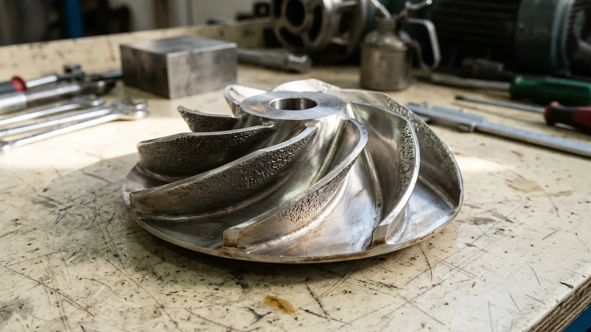
- Discharge Recirculation: High-pressure fluid at the impeller periphery turns backward, re-entering the impeller channels from the discharge tips. This shear flow creates high-velocity localized vortices that cause localized pressure depressions, triggering cavitation pitting on the pressure side of the impeller discharge vanes.
- Acoustic Signature: Generates characteristic irregular popping and crackling noise ("pumping gravel") that increases in intensity as the discharge valve is throttled further.
Mechanical Seal Face Thermal Distortion & Low Flushing Velocity
At low flow rates, fluid dwell time inside the casing increases:
- Low Flushing Velocity: API 682 Plan 11 or Plan 13 flush lines provide reduced circulation flow because the differential pressure across the pump is consumed across the throttled valve, resulting in inadequate seal chamber heat removal.
- Heat Checking: Frictional heat generated at the seal faces cannot dissipate, causing localized thermal expansion, micro-fracturing ("heat checking"), and blistering of silicon carbide and carbon seal faces.
4. The 5 Critical Symptoms & Failure Modes of Oversized Pumps
Symptom 1: Chronic Discharge Valve Throttling & Massive Electrical Waste
- Symptom Description: Discharge isolation or control valve is permanently locked at 30% - 50% open to prevent overflowing downstream vessels or tripping downstream equipment.
- Engineering Cost: Pumping power consumed across the throttled valve (ΔP_valve × Q) wastes lakhs of rupees in electrical energy while generating high valve seat erosion.
Symptom 2: High-Frequency Knocking Noise from Discharge Recirculation
- Symptom Description: Loud, irregular rumbling and knocking sounds originating from the pump casing volute and discharge neck, distinct from suction cavitation.
- Engineering Cost: Vane trailing edge cavitation pitting thins impeller shrouds, leading to structural fatigue fractures and catastrophic impeller destruction.
Symptom 3: Repeat Mechanical Seal Face Fracture & Heat Checking
- Symptom Description: Mechanical seals leak within 2 to 6 months of installation; disassembly reveals radial face chipping, carbon blistering, or severe thermal cracks.
- Engineering Cost: Unplanned hazardous chemical shutdowns, high spare parts inventory costs, and environmental containment risks.
Symptom 4: Elevated Bearing Housing Temperatures & High 1X / Vane-Pass Vibration
- Symptom Description: Bearing housing temperatures surge past 75^° - 85°C accompanied by high overall vibration (> 4.5 mm/s RMS) dominated by 1X rotational and vane-pass (Z × RPM) frequencies.
- Engineering Cost: High radial thrust accelerates bearing raceway spalling and cage fatigue, slashing bearing L_10h life from 50,000 hours to under 4,000 hours.
Symptom 5: Thermal Vaporization & Flashing Inside the Casing
- Symptom Description: Fluid temperature inside the casing rises significantly above ambient suction temperature; volatile chemicals flash into vapor, causing vapor locking and total loss of prime.
- Engineering Cost: Complete process disruption, dry-running of mechanical seals, and thermal shock damage to pump components.
5. Sanitary Materials of Construction & Cleanroom Standards
High-Tensile Ductile Iron (GGG 40) Armor Shells
- Casing Armor: High-tensile Ductile Iron (GGG 40 / EN-GJS-400-18) armored process pump casings engineered to withstand severe off-BEP pressure pulsations and nozzle loadings conforming to ISO 2858.
SS316L & Duplex Stainless Steel (UNS S31803) Precision Impellers
- Hydraulic Impellers: Investment-cast SS316L or Duplex SS (UNS S31803) impellers offering superior resistance to recirculation cavitation erosion and high structural stiffness.
Solid Isostatic PTFE & Transfer-Molded PFA Wet End Linings
- Chemical Process Wet Ends: 100% virgin isostatic solid PTFE or high-density transfer-molded PFA lined wet ends (4.5 - 6.0 mm thickness) providing total chemical inertness across 0 - 14 pH.
Monolithic Direct-Sintered Silicon Carbide (SSiC) Seals
- Mechanical Seals: Cartridge single or double mechanical seals featuring monolithic direct-sintered SSiC vs SSiC faces with Kalrez (FFKM) secondary elastomers.
6. Step-by-Step Oversized Pump Diagnostic & Correction SOPs
Execute these structured engineering SOPs when diagnosing and correcting oversized pumps:
Phase 1: Operating Flow, Head & Throttling Position Audit SOP
- Pressure & Current Measurement: Record suction pressure (P_s), discharge pressure before the valve (P_d1), discharge pressure after the valve (P_d2), and motor current (Amps).
- Valve Throttling Head Loss: Calculate head dissipated across the throttled valve:
Phase 2: Operating Point vs Catalog BEP Curve Mapping SOP
- BEP Flow Ratio Math: Locate current operating flow (Q_actual) and catalog best efficiency point flow (Q_BEP) on the manufacturer's performance curve.
- Operating Ratio Evaluation: Calculate Q_actual / Q_BEP. If ratio is < 0.60, the pump is confirmed to be severely oversized.
Phase 3: Radial Load & Shaft Deflection Verification SOP
- Radial Thrust Math: Compute dynamic radial force (F_r) and verify shaft deflection at the seal face is within the < 0.05 mm limit conforming to ISO 5199.
- Vibration Analysis: Take FFT spectrum vibration readings on bearing housings; verify presence of high 1X and vane-pass frequency harmonics.
Phase 4: Corrective Impeller Trimming & VFD Calculation SOP
- Target Sizing Math: Determine required unthrottled system head (H_2) at required flow (Q_2).
- Affinity Diameter Sizing: Calculate required trimmed impeller diameter:
- Safety Margin: Apply a +2% machining safety margin (D_2,mach = D_2 × 1.02) to ensure the pump does not become under-sized.
Phase 5: CNC Machining, Vane Under-Filing & Balancing SOP
- Precision Lathe Machining: CNC-machine impeller outer diameter down to specified D_2 dimension.
- Hydrodynamic Under-Filing: Hand-file or CNC-profile vane exit trailing edges into a smooth teardrop radius.
- Dynamic Rotor Balancing: Mount rotor assembly on a dynamic balancing machine; balance to ISO 5199 Grade G2.5 (< 1.0 g\cdotmm/kg).
Phase 6: On-Site Full-Open Valve Commissioning & Thermal Proof SOP
- Valve 100% Open Run: Commission modified pump with discharge valve 100% open.
- Verification Audit: Verify motor electrical current drops by 20% - 45%, vibration drops below 2.2 mm/s RMS, and bearing temperatures stabilize below 55°C.
7. Worked Gujarat Textile, Chemical & Utility Plant Case Studies
Case 1: Surat Textile Dyeing Liquor Circulation Oversized Pump Diagnostics
- Plant Context: A large synthetic fabric dyeing facility in Sachin GIDC (Surat) circulating hot dye liquor through stenters (160 m³/h required at 38 m head).
- Problem: An oversized 45 kW pump operated with its discharge valve 55% throttled; pump suffered mechanical seal face cracking every 60 days, high bearing vibration (6.8 mm/s RMS), and drew 41.5 kW continuously.
- Action Plan: Teflow engineering team diagnosed off-BEP operation (Q / Q_BEP = 0.48). Wide-open head was 54 m at full 230 mm impeller diameter. Calculated required trim:
- Outcome: Discharge valve opened 100%; motor power dropped from 41.5 kW to 26.8 kW (14.7 kW continuous power reduction); saved Rs 10,60,000 annually in electricity; vibration dropped to 1.4 mm/s RMS; zero seal failures across 24 consecutive operating months.
Case 2: Pandesara Polyester Plant Cooling Water Pump Off-BEP Vibration Fix
- Plant Context: A polyester yarn plant in Pandesara GIDC (Surat) operating two 400 m³/h cooling water booster pumps.
- Problem: Oversized pumps operated at 45% of BEP, generating severe discharge recirculation knocking noise and bearing overheating (82°C).
- Action Plan: Trimmed impellers by 14% in diameter and re-centered operating points inside the Preferred Operating Region (POR).
- Outcome: Knocking noise eliminated 100%; bearing temperatures stabilized at 48°C; total plant power savings reached 42 kW (Rs 30,20,000 annual savings).
Case 3: Vatva GIDC Chemical Reactor Circulation Impeller Trim Retrofit
- Plant Context: An agrochemical active facility in Vatva GIDC pumping corrosive solvent mixtures through a reactor heat exchanger loop.
- Problem: Throttled pump generated high radial shaft deflection (0.12 mm), shattering PFA-lined pump silicon carbide seal faces within 45 days.
- Action Plan: Calculated affinity trim, CNC-machined the PFA-lined impeller, and restored wear ring running clearances.
- Outcome: Shaft deflection dropped below 0.02 mm; mechanical seal operated without leakage over 22 consecutive operating months.
Case 4: Hazira Petrochemical Plant Hydrocarbon Booster Off-BEP Overhaul
- Plant Context: A petrochemical processing unit in Hazira operating two 600 m³/h hydrocarbon transfer pumps.
- Problem: Heavy discharge throttling caused casing fluid temperatures to rise by 18°C, creating volatile flashing risks.
- Action Plan: Executed oblique V-trimming on the impellers and installed variable speed drives.
- Outcome: Casing fluid temperature rise reduced to < 2°C; pump reliability reached 100%.
Case 5: Ankleshwar GIDC Solvent Condenser Chilled Water Pump Fix
- Plant Context: A pharmaceutical bulk drug plant in Ankleshwar GIDC circulating chilled brine.
- Problem: Oversized pump caused high control valve hunting and excessive pipe vibration.
- Action Plan: Trimmed impeller diameter by 11% to perfectly match maximum heat exchanger flow capacity.
- Outcome: Control valve hunting eliminated; motor current dropped by 29%.
Case 6: Dahej PCPIR Central Utility Boiler Feed Recirculation Elimination
- Plant Context: A utility boiler water station in Dahej PCPIR operating high-pressure feed pumps.
- Problem: Low-flow boiler demand during night shifts caused severe discharge recirculation and stage erosion.
- Action Plan: Installed an automated minimum flow recirculation valve (ARV) and trimmed first-stage booster impellers.
- Outcome: Stage erosion eliminated; continuous boiler feed availability restored across 26 consecutive operating months.
8. Step-by-Step Oversized Pump Correction Decision Matrix
Follow this structured engineering guide when correcting oversized pumps in Gujarat plants:
| Observed Plant Symptom | Identified Hydraulic Root Cause | Recommended Engineering Action |
|---|---|---|
| Discharge Valve Throttled > 40% | Excess generated head / Oversized pump | Precision CNC Impeller Diameter Trimming |
| Discharge Recirculation Knocking | Operating far left of BEP (< 60% Q_BEP) | Trim impeller or install VFD to restore BEP alignment |
| Repeat Seal Leaks / Face Chipping | Excessive radial force (F_r) & shaft deflection | Re-center pump at BEP and balance rotor to ISO 5199 Grade G2.5 |
| Elevated Bearing Temp (> 75°C) | Radial thrust overload on bearing raceways | Eliminate valve throttling via engineered impeller trim |
| Casing Fluid Temperature Rise | Hydraulic energy dissipation at low flow | Install minimum flow automatic recirculation valve (ARV) |
| Calculated Trim Ratio < 0.75 D_1 | Severely oversized for casing hydraulic size | Replace pump with smaller hydraulic casing model |
9. Comprehensive Master Oversized Pump Diagnostic Checklist
Execute this diagnostic protocol when auditing potentially oversized pumps in industrial plants:
Oversized Pump Diagnostic & Retrofit Quality Protocol
10. Summary & Corrective Pump Engineering Support in Gujarat
Eliminating the massive electrical power waste of throttled discharge valves, preventing destructive discharge recirculation cavitation, stopping cyclic shaft deflection that fractures mechanical seal faces, and guaranteeing rotating machinery reliability across Surat (Sachin GIDC, Pandesara), Ahmedabad (Vatva, Naroda, Odhav), Ankleshwar GIDC, and Dahej PCPIR—by utilizing first-principles off-BEP hydraulic diagnostics, precision CNC lathe impeller trimming, hydrodynamic vane under-filing, and dynamic rotor balancing conforming to ISO 5199, ISO 2858, IS 5120, and IS 1520 standards—is the proven engineering standard for industrial energy conservation.
Partnering directly with an established Gujarat rotating machinery manufacturer provides plant maintenance superintendents, energy managers, and utility engineers with immediate technical access to on-site off-BEP diagnostic audits, CNC impeller machining, dynamic balancing machines, and genuine spares. Our technical engineers provide on-site pump vibration surveys, affinity trimming proposals, and complete turnkey retrofit services.
Teflow Pumps operates a specialized chemical and industrial machinery manufacturing facility in Ahmedabad, providing engineered impeller trimming, PFA-lined process pumps, solid PTFE pumps, PVDF centrifugal pumps, precision mechanical seals, dynamic rotor balancing, and genuine rotating equipment spares across Gujarat conforming to ISO 5199, ISO 2858, IS 5120, and API 685 standards.
- Direct Technical & Emergency Helpline: +91 98251 62709
- WhatsApp Technical Desk: Share pump nameplate photos, throttled valve position (%), motor operating current (Amps), suction/discharge pressure readings (bar), or required operating flow (m³/h) to wa.me/919825162709 for immediate technical review, off-BEP diagnostic evaluation, and formal quotation.
- Request an On-Site Pump Diagnostic & Impeller Trimming Survey: Contact our senior rotating equipment engineers for plant pump surveys, energy audit proposals, and formal quotation. Our engineering team conducts comprehensive hydraulic duty audits, calculates exact impeller trim dimensions, dynamically balances rotors, and certifies modified pump assemblies to ensure maximum uptime across Gujarat's industrial processing clusters. We provide rapid technical evaluations, on-site plant surveys, and formal quotes.