
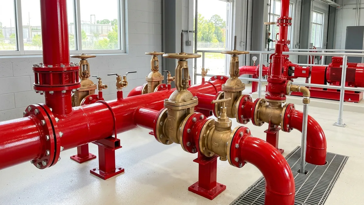
Fire Pump Testing per NFPA 20 & NFPA 25: Complete Plant Inspection Checklist, Flow Diagnostics & Maintenance Protocol
A definitive rotating equipment compliance standard, NFPA 20 installation guide, and NFPA 25 annual flow testing manual for plant maintenance engineers, safety officers (HSE), and facility operations managers across Ahmedabad, Sanand, Changodar, Vatva, Dahej, Ankleshwar, Hazira, and Gujarat.
Quick Answer
In the expansive industrial parks, chemical processing clusters, pharmaceutical manufacturing campuses, and engineering complexes of Gujarat—spanning Ahmedabad (Sanand, Changodar, Vatva, Naroda), Dahej PCPIR, Ankleshwar, and Hazira—stationary fire pump systems form the core defensive barrier safeguarding multi-crore physical assets, personnel, and production continuity against industrial fire disasters. Plant safety officers, maintenance heads, and insurance risk surveyors face a critical operational mandate: fire pumps remain idle for over 99% of their operating life, making them vulnerable to shaft binding, impeller scale buildup, mechanical seal drying, gland packing hardening, battery voltage decay, and diesel fuel degradation. Ensuring that electric-motor-driven and diesel-engine-driven fire pumps start instantly and deliver rated hydraulic flow during an emergency requires strict adherence to NFPA 20 (Installation standard) and NFPA 25 (Standard for Inspection, Testing, and Maintenance of Water-Based Fire Protection Systems), in harmonization with IS 1520 and IS 5120 Indian standards. Conforming to these standards mandates a structured protocol: weekly no-flow churn tests (10 minutes for electric, 30 minutes for diesel), monthly jockey pump pressure switch verifications, and comprehensive annual 3-point performance flow tests across three hydraulic benchmarks: Churn (zero flow, shut-off head ≤ 140% of rated), 100% Rated Flow at rated net pressure, and 150% Peak Overload Flow delivering at least 65% of rated net pressure.
Key Takeaways
- Execute Weekly No-Flow Churn Testing. Run electric fire pumps for 10 minutes and diesel fire pumps for 30 minutes weekly to verify auto-start and casing cooling.
- Conduct Annual 3-Point Hydraulic Performance Flow Testing. Verify churn pressure (≤ 140%), 100% rated flow, and 150% peak flow (≥ 65% rated net head).
- Calibrate Jockey Pump Cut-In and Cut-Out Pressure Switches. Prevent main fire pump nuisance cycling by setting jockey cut-in 0.7 bar below normal plant pressure.
- Enforce Dynamic Balancing to ISO 5199 Grade G2.5. Precision balance horizontal split-case and vertical turbine fire pump impellers to eliminate destructive vibration.
Introduction
Across Gujarat's premier industrial corridors—including Ahmedabad's manufacturing belts in Sanand, Changodar, Vatva, and Naroda, as well as Dahej PCPIR, Ankleshwar GIDC, and Hazira—industrial plants store thousands of tonnes of combustible raw materials, flammable solvents, plastics, and finished goods.
Plant safety officers, maintenance heads, and EPC fire protection leads encounter significant operational challenges:
- The Standstill Vulnerability: Fire pumps operate under severe standstill conditions. Unlike utility process pumps that circulate fluid continuously, fire pumps remain idle for months. Without disciplined weekly churn runs and annual full-load flow testing, line-shaft bearings corrode, mechanical seals seize, stuffing box gland packings bake onto shafts, and controller pressure transducers drift out of calibration.
- The False-Security Trap: Many facilities conduct only no-load electric motor starts, assuming that a pump that spins at zero flow will deliver its rated water flow during an emergency. When full sprinkler and hydrant flow is demanded, worn wear rings, clogged impellers, or cavitating suction lines cause discharge pressure to collapse below fire fighting thresholds.
- The Engineering Standard: Implementing a rigorous inspection, testing, and maintenance (ITM) program conforming strictly to NFPA 20, NFPA 25, IS 1520, and IS 5120 standards—verifying weekly churn starts, annual 3-point hydraulic flow curves (100% and 150% duty points), pitot tube discharge calculations, dynamic rotor balancing to ISO 5199 Grade G2.5, and dual-plane laser alignment—guarantees instantaneous fire water delivery and full insurance compliance.
2. Master NFPA 20 & NFPA 25 Fire Pump Testing Matrix
Review the testing intervals, engineering requirements, and acceptance criteria specified under NFPA 20 and NFPA 25:
| Testing Frequency | Equipment & Component Tested | Operational Protocol & Test Method | NFPA 25 Acceptance Criteria |
|---|---|---|---|
| Weekly | Electric Motor Driven Fire Pump | No-Flow Churn Run (Automatic Start via Solenoid) | Minimum 10 min run; casing relief valve flowing water |
| Weekly | Diesel Engine Driven Fire Pump | No-Flow Churn Run (Auto Start via Dual Batteries) | Minimum 30 min run; cooling heat exchanger flowing |
| Monthly | Jockey / Pressure Maintenance Pump | Manual & Auto Start-Stop Pressure Cycling | Maintains line pressure; cut-in/cut-out within spec |
| Monthly | Fire Pump Controller & Transducers | Pressure Sensing Line Flush & Battery Voltage Check | Zero air locks; battery float voltage ≥ 26.4 V |
| Annual | Fire Pump 3-Point Flow Test (Point 1) | Zero Flow / Churn Shut-Off Pressure Test | Shut-off head ≤ 140% of rated net pressure |
| Annual | Fire Pump 3-Point Flow Test (Point 2) | 100% Rated Flow Test via Hose Header / Flow Meter | Delivers ≥ 100% rated flow at 100% rated head |
| Annual | Fire Pump 3-Point Flow Test (Point 3) | 150% Peak Overload Flow Test via Hose Header | Delivers ≥ 150% rated flow at ≥ 65% rated head |
| Annual | Vibration & Mechanical Alignment | Dual-Plane Laser Alignment & FFT Spectrum Analysis | Vibration velocity < 2.8 mm/s RMS (IS 1520 Zone A) |
3. The Hydraulic Physics, Pitot Tube Math & Performance Degradation Curves
The NFPA 20 3-Point Performance Curve Mechanics (Churn, 100%, 150%)
NFPA 20 defines a standardized hydraulic head-capacity (H-Q) curve envelope for all certified stationary fire pumps:
- Point 1 (Churn / Shut-Off Head): At zero discharge flow (Q = 0), the maximum shut-off head (H_churn) must not exceed 140% of rated head:
Interactive Engineering Hydraulic Sizer
Live ISO 5199 / API 610 Dynamic Engine- Point 2 (100% Rated Flow Point): At rated flow (Q_rated), the pump must deliver at least 100% of rated net head:
- Point 3 (150% Peak Overload Flow Point): At 150% of rated flow (1.50 · Q_rated), the pump must deliver at least 65% of rated net head:
- NFPA 25 Degradation Limit: During annual re-testing, the actual measured head-flow curve must not degrade by more than 5% below the original manufacturer nameplate or shop test curve at any test point.
Pitot Tube Orifice Flow Math (Q = 29.83 · c · d² · √(P))
When conducting annual flow tests using smooth bore fire nozzles connected to the external test header:
To convert to metric flow (Q_metric in m³/h):
Where:
- c is the nozzle discharge coefficient (typically 0.97 for Underwriters Laboratories smooth bore test nozzles).
- d is the internal nozzle diameter in inches (e.g., 1.75 in or 2.50 in).
- P is the velocity pressure measured at the center of the discharge stream using a calibrated hand-held Pitot tube gauge in psi.
Jockey Pump Hydraulic Sizing & Pressure Switch Tuning Math
The jockey pump (pressure maintenance pump) restores minor pressure losses caused by underground piping joint seepage:
- Sizing Rule: Sized to deliver approximately 1% of main fire pump rated flow (typically 2 - 5 m³/h) at a discharge pressure slightly higher than the main pump churn pressure.
- Pressure Switch Calibration Ladder:
- System Normal Static Pressure: e.g., 10.0 bar. - Jockey Pump Cut-Out (Stop): 10.0 bar. - Jockey Pump Cut-In (Start): 9.3 bar (0.7 bar below normal). - Main Electric Fire Pump Cut-In (Start): 8.3 bar (1.0 bar below jockey start). - Standby Diesel Fire Pump Cut-In (Start): 7.3 bar (1.0 bar below electric start).
Casing Relief Valve & Circulation Cooling Sizing
During no-flow churn testing, the entire power input of the electric motor is converted into heat within the trapped casing water volume:
- Automatic Circulation Relief Valve: NFPA 20 mandates an automatic casing relief valve (minimum size 3/4 in for pumps up to 2500 GPM, 1 in for larger pumps) that continuously discharges cold water to open drain, preventing water vaporization and internal impeller seizure.
4. The 4 Critical Failure Modes in Industrial Fire Pumping Systems
Failure Mode 1: Failure to Auto-Start on System Pressure Drop
- Root Cause: Clogged controller pressure sensing lines, accumulated sediment in bourdon tubes, or defective pressure transducer solenoids.
- Engineering Solution: Install dual brass pressure sensing lines with pulsation dampeners and flushing drain valves conforming to NFPA 20 Section 4.30.
Failure Mode 2: Hydraulic Performance Decay Below NFPA 25 95% Curve
- Root Cause: Excessive internal casing wear ring clearances (clearance > 0.80 mm vs 0.25 mm design), impeller vane erosion, or suction strainer obstruction.
- Engineering Solution: Precision CNC machining of replacement bronze wear rings (LTB2 Lead Tin Bronze), dynamic balancing to ISO 5199 Grade G2.5, and casing internal ceramic recoating.
Failure Mode 3: Casing Overheating from Blocked Circulation Relief Valves
- Root Cause: Plant operators closing or plugging casing relief lines to prevent water spillage on pump house floors during weekly tests.
- Engineering Solution: Route dedicated 1-inch copper or SS316 relief drain lines directly to an open industrial floor drain or water storage sump.
Failure Mode 4: Diesel Engine Starting Battery & Fuel Day Tank Starvation
- Root Cause: Lead-acid starting battery sulfation, lack of float charging, or microbial growth (algae) clogging diesel fuel primary filters.
- Engineering Solution: Weekly battery specific gravity checks, dual redundant automatic battery chargers, and bi-monthly diesel fuel filtration.
5. Fire Pump Architecture, Materials & Sealing Configurations
Horizontal Split-Case Centrifugal Fire Pumps (IS 1520 / IS 5120)
- Double-Suction Horizontal Split-Case: The industry standard for heavy industrial facilities (Q = 100 to 1000 m³/h, H = 70 to 160 m). Horizontally split casing allows upper half removal for inspection without disconnecting suction or discharge piping.
Vertical Turbine Sump & Basin Fire Pumps (IS 1520)
- Vertical Turbine Pumps: Multi-stage submerged bowl pumps used when water supply is stored in below-grade underground sumps or open raw water reservoirs where suction lift is required.
Cast Iron (FG 260), Ductile Iron & LTB2 Bronze Trim
- Fire Pump Metallurgy: Heavy-duty Cast Iron (FG 260) or Ductile Iron (GGG 40) casings paired with dynamic balanced Lead Tin Bronze (LTB2) or SS316 impellers conforming to IS 1520 and IS 5120 standards with high-tensile carbon steel shafts with stainless sleeves.
Graphited PTFE Gland Packing vs Cartridge Mechanical Seals
- Sealing Standards: NFPA 20 traditionally recommends graphited PTFE gland packing (allowing a cooling leakage of 30-60 drops per minute) to ensure fail-safe operation during power loss, or API 682 cartridge mechanical seals featuring silicon carbide faces with external bypass flushing.
6. Step-by-Step NFPA 25 Fire Pump Testing SOPs
Execute these structured engineering SOPs when testing industrial fire pump systems:
Phase 1: Weekly No-Flow Churn Testing & Casing Cooling SOP
- Visual Pre-Check: Verify suction and discharge gate/butterfly valves are locked in fully open position. Check oil level in bearing housings.
- Electric Pump Churn Run: Initiate auto-start by opening controller test drain valve. Run motor for minimum 10 minutes. Verify casing circulation relief valve flows water freely and motor current is balanced across all three phases.
- Diesel Engine Churn Run: Auto-start diesel engine using Battery Bank 1; run for minimum 30 minutes. Verify cooling loop heat exchanger water discharge temperature is < 65°C and engine oil pressure is > 3.5 bar. Re-test with Battery Bank 2 on alternating weeks.
Phase 2: Monthly Controller, Battery & Jockey Pump Inspection SOP
- Jockey Cycling: Drop header pressure manually; confirm jockey pump starts at 9.3 bar and stops at 10.0 bar without water hammer.
- Battery Health: Measure individual pilot cell electrolyte specific gravity (≥ 1.260) and battery terminal float voltage (≥ 26.4 V on 24V systems).
Phase 3: Annual 3-Point Hydraulic Flow Testing via Test Header SOP
- Setup: Connect calibrated test hoses and Underwriters smooth bore nozzles (or calibrated ultrasonic flow meter) to external multi-valve test header.
- Test Point 1 (Churn): Record suction pressure (P_s), discharge pressure (P_d), and RPM at zero flow. Confirm net head ≤ 140% of rated.
- Test Point 2 (100% Flow): Open test valves until flow meter indicates 100% rated flow (Q_rated). Record suction pressure, discharge pressure, engine RPM, and motor current. Verify net head ≥ 100% of rated head.
- Test Point 3 (150% Flow): Open additional valves to achieve 150% rated flow (1.5 · Q_rated). Verify discharge net head is ≥ 65% of rated head.
- Plot Curve: Plot measured 3-point curve against manufacturer shop test baseline; confirm < 5% degradation.
Phase 4: Flow Meter & Pitot Tube Discharge Measurement Calibration SOP
- Pitot Gauge Measurement: Hold pitot tube blade at nozzle orifice center (1/2 internal diameter distance). Record velocity pressure (P_psi) and calculate flow using orifice equation.
- Flow Meter Correlation: Compare pitot calculations against in-line magnetic or ultrasonic flow meters to verify flow measurement accuracy within ± 2%.
Phase 5: Diesel Engine Governor & Heat Exchanger Cooling Audit SOP
- Governor Response: Under sudden 150% flow load, verify diesel governor maintains engine speed within ± 5% of rated RPM (2900 RPM or 1750 RPM).
- Cooling Loop Strainer: Clean primary and bypass raw water cooling strainers on diesel heat exchanger manifold.
Phase 6: Full System Dynamic Balancing & Laser Alignment Re-Proof SOP
- Laser Shaft Alignment: Conduct dual-plane laser alignment; verify coupling parallel offset is < 0.03 mm and angular deviation < 0.04 mm/100 mm.
- Vibration FFT Proof: Record overall vibration at bearing housings; confirm velocity is < 2.8 mm/s RMS (IS 1520 / ISO 5199 Zone A).
7. Worked Gujarat Industrial Park, Chemical & Pharmaceutical Case Studies
Case 1: Sanand GIDC Automotive Manufacturing Fire Pump Annual Testing
- Plant Context: An automotive assembly plant in Sanand GIDC operating a 450 m³/h (125 m head) horizontal split-case electric fire pump with diesel standby.
- Problem: During annual insurance survey, the electric pump delivered only 68 m head at 150% flow (failing NFPA 25 65% minimum requirement of 81.2 m).
- Diagnostic Evaluation: Internal casing inspection revealed wear ring clearance had expanded to 1.20 mm due to abrasive silt accumulation in the fire water reservoir.
- Corrective Action: Teflow engineering team overhauled the pump:
- Precision CNC machined replacement LTB2 bronze wear rings with tight 0.25 mm radial clearance. - Dynamically balanced double-suction impeller to ISO 5199 Grade G2.5. - Replaced packing with low-friction graphited PTFE.
- Outcome: Re-test delivered 92.5 m head at 150% flow (74% of rated head); passed NFPA 25 annual audit with 100% compliance.
Case 2: Vatva GIDC Chemical Complex Horizontal Split-Case Fire Pump Overhaul
- Plant Context: A specialty dyestuff plant in Vatva GIDC operating a 20-year-old 300 m³/h fire pump.
- Problem: High shaft vibration (7.8 mm/s) during weekly churn runs caused gland packing blowouts and shaft scoring.
- Action Plan: Extracted rotating assembly; straightened shaft on hydraulic press, fitted SS316 hard chrome-plated sleeves, and balanced rotor on electronic balancing machine.
- Outcome: Vibration velocity dropped to 1.2 mm/s RMS; zero gland heating during 30-minute churn testing.
Case 3: Dahej PCPIR Petrochemical Terminal Diesel Engine Fire Pump Restoration
- Plant Context: A bulk hydrocarbon storage terminal in Dahej PCPIR operating a 600 m³/h diesel engine fire pump.
- Problem: Diesel engine failed to crank automatically on Battery Bank 2 due to oxidized contactor terminals and contaminated fuel filters.
- Action Plan: Replaced starting solenoids, installed dual smart float chargers, cleaned fuel day tank, and tuned electronic speed governor.
- Outcome: Instantaneous auto-start within 8 seconds on both battery banks; successfully delivered 900 m³/h (150% load) during full flow test.
Case 4: Changodar Industrial Estate Pharmaceutical Warehouse Jockey Pump Fix
- Plant Context: A pharmaceutical logistics warehouse in Changodar experiencing frequent nuisance starting of the main 110 kW electric fire pump.
- Problem: Jockey pump pressure switch had drifted, setting cut-in pressure below main pump cut-in threshold.
- Action Plan: Re-calibrated pressure switches (Jockey: Start 9.2 bar, Stop 10.0 bar; Main Pump: Start 8.0 bar).
- Outcome: Main fire pump nuisance cycling eliminated 100%; system pressure held stable.
Case 5: Ankleshwar GIDC Agrochemical Facility Vertical Turbine Sump Pump Rebuild
- Plant Context: An agrochemical plant in Ankleshwar GIDC operating a 3-stage vertical turbine fire pump suspended in a 6 meter deep water sump.
- Problem: Severe line-shaft cutless rubber bearing wear caused shaft binding during dry seasons.
- Action Plan: Disassembled pump column, replaced rubber line-shaft bearings with water-lubricated composite bearings, and renewed bronze bowl wear rings.
- Outcome: Full nameplate flow restored; smooth starting with zero motor overload.
Case 6: Hazira Heavy Engineering Plant Multi-Pump Header Flow Balancing
- Plant Context: A heavy fabrication shipyard in Hazira operating two 500 m³/h fire pumps in parallel.
- Problem: Unequal discharge check valve spring tensions caused Pump 1 to deadhead while Pump 2 carried full flow.
- Action Plan: Overhauled dual swing check valves, installed matched spring disc non-return valves, and balanced discharge piping headers.
- Outcome: Symmetrical flow sharing achieved (495 m³/h on Pump 1, 505 m³/h on Pump 2) at full header demand.
8. Step-by-Step NFPA 25 Fire Pump Testing Decision Matrix
Follow this structured engineering guide when evaluating fire pump operational issues during plant audits:
| Observed Testing Condition | Identified Root Cause | Corrective Engineering Action Protocol |
|---|---|---|
| Pump fails to auto-start on pressure drop | Clogged sensing line or faulty transducer | Flush sensing line; test controller solenoid valves |
| Shut-off head exceeds 140% of rated head | Oversized impeller trim or high motor speed | Audit impeller diameter; trim impeller or adjust RPM |
| 100% flow delivered but head < 95% baseline | Worn casing wear rings or internal leakage | Replace wear rings (LTB2 bronze); restore clearances |
| 150% flow head drops below 65% rated head | Suction line cavitation or impeller blockage | Inspect suction strainer; remove debris; check NPSH |
| Casing runs hot (> 60°C) during churn | Blocked or closed circulation relief valve | Clear relief valve piping; verify continuous cooling water |
| Excessive vibration (> 4.5 mm/s RMS) | Rotor unbalance or coupling misalignment | Laser align shaft; dynamically balance to ISO 5199 G2.5 |
9. Comprehensive Master NFPA 25 Plant Fire Pump Inspection Checklist
Execute this quality verification protocol during weekly churn tests and annual full-load flow testing:
NFPA 20 & NFPA 25 Fire Pump Inspection & Testing Protocol
10. Summary & Fire Pump Testing Support in Gujarat & India
Maintaining complete industrial fire pump readiness conforming strictly to NFPA 20, NFPA 25, IS 1520, and IS 5120 standards—executing disciplined weekly no-flow churn testing, monthly jockey pump calibration, and comprehensive annual 3-point performance flow testing across Ahmedabad (Sanand, Changodar, Vatva, Naroda), Dahej PCPIR, Ankleshwar, and Hazira—by precision CNC machining of bronze wear rings, dynamic rotor balancing to ISO 5199 Grade G2.5, and dual-plane laser shaft alignment—is the proven engineering standard safeguarding industrial infrastructure.
Partnering directly with an established Gujarat rotating machinery specialist provides plant safety officers, maintenance engineers, and facility heads with immediate technical access to calibrated fire pump flow testing equipment, ultrasonic flow meters, Pitot tube test headers, replacement bronze impellers, dynamic balancing facilities, and genuine spares dispatched directly from our Ahmedabad manufacturing works. Our technical engineers provide comprehensive fire pump audits, annual performance flow tests, and turnkey overhauls.
Teflow Pumps operates a specialized rotating equipment manufacturing and service facility in Ahmedabad, providing engineered horizontal split-case pumps, vertical turbine pumps, multistage boiler feed pumps, chemical process pumps, precision dynamic rotor balancing, laser alignment, and genuine rotating equipment spares across Gujarat and India conforming to IS 1520, IS 5120, ISO 5199, and API 685 standards.
- Direct Technical & Emergency Helpline: +91 98251 62709
- WhatsApp Technical Desk: Share fire pump nameplate details, rated flow (m³/h or GPM), rated head (m or bar), engine/motor horsepower, or current annual test reports to wa.me/919825162709 for immediate technical review, hydraulic curve evaluation, and formal quotation.
- Request an On-Site Fire Pump Audit & Performance Flow Test Survey: Contact our senior rotating equipment engineers for plant fire pump surveys, annual flow testing proposals, and formal quotation. Our engineering team conducts comprehensive 3-point flow evaluations, verifies NFPA 20 & 25 criteria, provides custom pump overhauls, and tests overhauled rotating machinery to ensure total fire protection readiness across Gujarat's industrial parks and manufacturing zones. We provide rapid technical evaluations, on-site plant surveys, and formal quotes.