
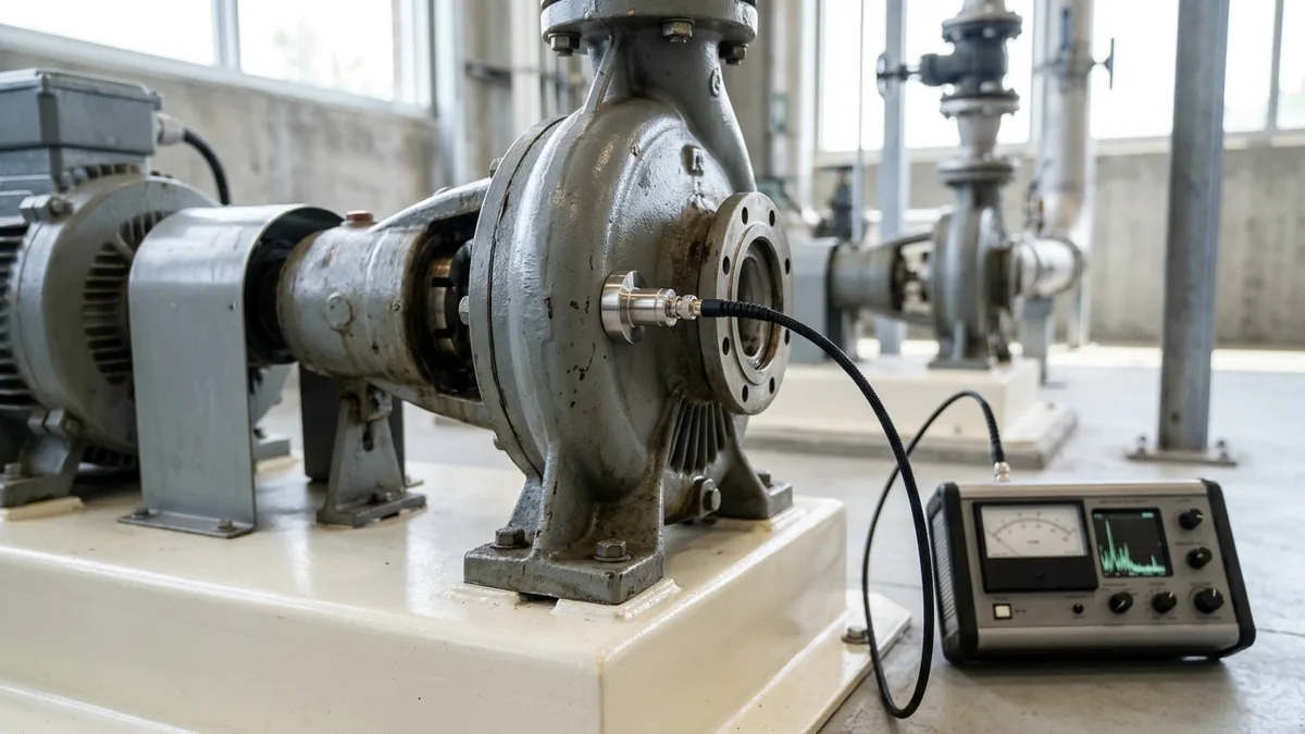
Hydraulic & Centrifugal Pump Cavitation Symptoms: Acoustic Diagnosis, Micro-Jet Physics & Field Suction Tests
A definitive technical troubleshooting guide, cavitation fluid mechanics manual, and acoustic field testing protocol for plant maintenance engineers, hydraulic systems leads, and rotating equipment reliability specialists across Surat, Ahmedabad, Rajkot, Vadodara, and Gujarat.
Quick Answer
In textile dyeing and printing mills, synthetic fiber extrusion plants, chemical reactor units, and precision CNC machine tool hydraulic power packs across Gujarat—such as in Surat, Ahmedabad, Rajkot, Ankleshwar, and Vadodara—centrifugal process pumps and hydraulic oil power units frequently suffer from destructive cavitation. When the static pressure at the pump suction nozzle drops below the fluid vapor pressure (P_suction < P_vapor), localized liquid boils into millions of microscopic vapor bubbles. As these bubbles travel into higher pressure regions across the impeller vanes, they violently collapse in picoseconds (t < 10^-6 s), generating localized micro-jets with velocities exceeding 1000 m/s and localized shockwave pressures surpassing 1000 to 1500 MPa (150,000 psi). This microscopic water hammer strips protective passivation layers, gouges deep honeycomb sponge-like pits into CF8M (SS316) and cast iron impellers, shatters mechanical seal faces, and generates the unmistakable acoustic sound of pumping gravel or rattling marbles. Conforming to ISO 5199, ISO 2858, IS 5120, IS 1520, API 610, and Hydraulic Institute (HI 1.3) standards, diagnosing and eliminating cavitation requires systematic Net Positive Suction Head (NPSHa vs NPSHr) margin verification (≥ 0.6 m), acoustic ultrasonic testing, suction line friction reduction, and precision impeller trimming.
Key Takeaways
- Acoustic "Gravel Rattle" is the Classic Signature of Suction Cavitation. The sound originates from millions of microscopic vapor bubbles collapsing at supersonic speeds.
- Maintain a Minimum NPSH Margin (NPSHa - NPSHr ≥ 0.6 m). Operating without adequate margin guarantees continuous vapor bubble inception.
- High-Frequency Broadband Vibration (1 - 5 kHz) Confirms Cavitation. Unlike unbalance (1X) or misalignment (2X), cavitation creates a raised high-frequency noise floor.
- Pitted Impeller Vane Inlets Signal Inadequate Suction Pressure. Sponge-like metal loss on the low-pressure vane underside is the definitive physical proof of classical cavitation.
Introduction
In continuous textile processing and jet dyeing houses, heavy engineering manufacturing facilities, chemical process plants, and industrial hydraulic power pack installations across Surat, Ahmedabad, Rajkot, Vadodara, and Gujarat, rotating pumps operate under demanding suction lift, high operating temperatures, and varying fluid viscosities.
Plant managers, maintenance superintendents, and reliability engineers face severe recurring hurdles:
- The Destructive Nature of Cavitation: Cavitation is not merely noise; it is a violent mechanical destruction mechanism. Operating a cavitating pump for just 500 hours can completely consume stainless steel impeller vanes, erode volute cutwaters, and destroy mechanical seal silicon carbide faces.
- The Diagnostic Confusion: Field maintenance teams frequently confuse cavitation noise with mechanical bearing damage, pipe vibration, or internal valve chatter, leading to wasted bearing replacements that fail to resolve the underlying hydraulic starvation.
- The Engineering Standard: Enforcing a comprehensive hydraulic diagnostic and suction optimization protocol conforming to ISO 5199, ISO 2858, IS 5120, IS 1520, API 610, and Hydraulic Institute (HI 1.3) standards—mandating rigorous NPSH margin auditing (≥ 0.6 m), suction line re-engineering, anti-vortex baffles, and leading-edge impeller profiling—eliminates vapor bubble collapse and extends pump MTBF beyond 35,000 operating hours.
2. Master Pump Cavitation Types, Symptoms & Diagnostic Matrix
Review the primary cavitation classifications, physical acoustic signatures, and damage locations:
| Cavitation Type | Primary Hydraulic Trigger Mechanism | Physical Damage Location | Characteristic Acoustic & Gauge Symptoms |
|---|---|---|---|
| Classical Suction Cavitation | NPSHa < NPSHr (Low Suction Head) | Impeller Vane Inlet (Low-Pressure Underside) | Loud "gravel rattling" noise; steady low suction vacuum gauge |
| Discharge Cavitation (Tip Stall) | Operating Near Shutoff Head (< 10% BEP) | Impeller Vane Tips & Volute Cutwater Tongue | High-pitched pinging; discharge pressure gauge fluctuating wildly |
| Suction Recirculation Cavitation | High Suction Specific Speed (N_ss > 11,000) at Low Flow | Impeller Eye Inlet Shroud & Outer Vane Tips | Deep rhythmic thumping noise; heavy 1X low-frequency vibration |
| Air Ingestion / Entrainment | Suction Vortex / Loose Flange Gasket | Uniform Micro-Pitting on Vanes; Mechanical Seal | Sucking slurping sound; sporadic pressure collapse; seal dry run |
| Thermal Flashing Cavitation | Pumping Near Boiling Point (T_fluid ≈ T_sat) | Entire Impeller Eye & Mechanical Seal Chamber | Sudden total loss of prime; steam blowing from gland vent |
3. The Fluid Dynamics & Micro-Jet Physics of Bubble Collapse
Vapor Bubble Inception & The Rayleigh-Plesset Equation
When local static liquid pressure drops below the saturation vapor pressure (P_local < P_vapor), microscopic vapor cavities nucleate and grow according to the Rayleigh-Plesset bubble dynamics equation:
Interactive Net Positive Suction Head (NPSHa) Sizer
Live ISO 5199 / API 610 Dynamic Engine- Bubble Growth Dynamics: As liquid accelerates across the leading edge of an impeller vane, static pressure drops to its absolute minimum. The microscopic vapor nucleus expands explosively to hundreds of times its original radius in less than 0.5 milliseconds.
Supersonic Micro-Jet Impact Dynamics (v_jet> 1000 m/s, P_shock> 1000 MPa)
As the vapor bubble travels along the vane into the higher static pressure region:
- Asymmetrical Collapse: The side of the bubble furthest from the metallic surface collapses faster, forming a high-speed liquid micro-jet that pierces the bubble center.
- Micro-Jet Impact Velocity: The micro-jet strikes the metal surface at velocities v_jet = 1000 - 1400 m/s.
- Water Hammer Shockwave: The resulting localized shockwave exerts instantaneous compressive stresses exceeding 1000 to 1500 MPa (150,000 psi). Because this localized stress far exceeds the yield strength of cast iron (200 MPa) and stainless steel (520 MPa), surface grains are dislodged by mechanical fatigue, creating distinct sponge-like cavitation craters.
Net Positive Suction Head Hydrodynamics (NPSHa = [P_s - P_v] / [ρg] + [V_s²] / [2g] ± Z)
Available Net Positive Suction Head (NPSHa) represents the total absolute pressure head available at the suction nozzle above the vapor pressure:
- Cavitation Inception Rule: Cavitation begins when NPSHa ≤ NPSHr_3% (where NPSHr_3% is the manufacturer required head for a 3% developed head drop). Conforming to API 610 and HI 1.3, a minimum margin ratio of NPSHa / NPSHr ≥ 1.3 (or NPSHa - NPSHr ≥ 0.6 to 1.0 m) must be maintained across all operating flows.
Suction Specific Speed (N_ss = [N √(Q)] / [NPSHr^0.75]) & Recirculation Instability
Suction Specific Speed (N_ss) characterizes the suction geometry aggressiveness of an impeller:
- Recirculation Threshold: Impellers engineered with large eye diameters for very low NPSHr exhibit high suction specific speeds (N_ss > 11,000 US Units). When operated at part-load (< 70% BEP), fluid cannot enter smoothly, initiating violent suction recirculation vortices that cause severe low-frequency cavitation and surge.
4. The 4 Critical Cavitation Failure Modes in Gujarat Industrial Facilities
Failure Mode 1: Classic Suction Cavitation from Inadequate NPSHa
- Failure Mechanism: High suction line friction losses, undersized suction piping, or high fluid temperature drop NPSHa below NPSHr. Vapor bubbles form at the impeller inlet and collapse on the low-pressure vane underside.
- Engineering Solution: Increase suction pipe diameter, eliminate restrictive elbows, elevate suction supply head, or install an inducer.
Failure Mode 2: Discharge Cavitation from Throttling Near Shutoff
- Failure Mechanism: Operating a high-head pump with the discharge valve heavily throttled (< 10% BEP) traps fluid inside the volute. High-velocity fluid shears past the casing cutwater tongue, forming localized vapor bubbles that collapse against the cutwater.
- Engineering Solution: Install a minimum continuous thermal bypass line or implement VFD speed control.
Failure Mode 3: Suction Recirculation Cavitation at Low Part-Loads
- Failure Mechanism: Running oversized pumps at part-load causes fluid to flow backward out of the impeller eye in a high-speed rotating vortex, generating heavy acoustic thumping and pitting the outer eye diameter.
- Engineering Solution: Retrofit with an impeller featuring lower N_ss (< 9000) or install flow-straightening suction vanes.
Failure Mode 4: Air Ingestion Cavitation from Shallow Sump Vortices
- Failure Mechanism: Shallow submergence in cooling tower basins creates swirling surface whirlpools that ingest atmospheric air into the pump nozzle, causing severe pressure hunting and seal dry running.
- Engineering Solution: Install submerged anti-vortex cross baffle plates conforming to Hydraulic Institute (HI 1.3) guidelines.
5. Sanitary Materials of Construction & Cleanroom Standards
CF8M (SS316) & Duplex SS 2205 Impellers vs Standard Cast Iron
- Cavitation Erosion Resistance: Forged Duplex SS 2205 (UNS S32205) and cast CF8M (SS316) offer over 8× higher cavitation erosion resistance compared to standard Grade FG 260 cast iron due to high work-hardening capacity and superior micro-ductility.
Monolithic Direct-Sintered Silicon Carbide (SSiC) for Seal Cavitation Protection
- Mechanical Seal Faces: Direct-sintered monolithic Silicon Carbide (SSiC, 2800 HV) stationary and rotating rings resisting mechanical face chattering and dry-running thermal shock during transient cavitation events.
Piezoelectric Accelerometers & High-Frequency Acoustic Sensors
- Vibration Diagnostics: Studio-grade piezoelectric accelerometers (100 mV/g) with high-frequency resonance detection (> 10 kHz) and ultrasonic acoustic detectors (38 kHz) detecting micro-bubble collapse long before physical metal pitting occurs.
Anti-Vortex Baffle Plates & Low-Loss Suction Piping Geometry
- Suction Geometry: Stainless steel cruciform anti-vortex baffles, long-radius elbows positioned > 5 · D_pipe upstream of suction nozzle, and eccentric reducers installed flat-on-top preventing air pocket formation.
6. Step-by-Step Field Cavitation Diagnostic & Suction Correction SOPs
Execute these structured engineering SOPs when diagnosing and eliminating pump cavitation:
Phase 1: Field Acoustic & Stethoscope Noise Profiling SOP
- Acoustic Listening: Place an industrial mechanical stethoscope or ultrasonic detector on the pump suction nozzle, bearing frame, and volute casing.
- Noise Differentiation:
- "Gravel Rattle / Cracking Noise" at suction: Classical Suction Cavitation. - "Deep Rhythmic Thumping" at low flow: Suction Recirculation. - "High-Pitched Squeal / Pinging" at discharge: Discharge Tip Cavitation. - "Smooth Whine": Mechanical Bearing Damage.
Phase 2: High-Frequency Vibration FFT Spectrum Analysis (1 - 5 kHz) SOP
- Sensor Mounting: Mount tri-axial piezoelectric accelerometers on pump bearing housings.
- FFT Spectrum Analysis: Inspect the high-frequency domain (1000 - 5000 Hz). A characteristic elevated, wide "haystack" broadband noise floor confirms vapor bubble micro-jet collapse.
Phase 3: Field Net Positive Suction Head (NPSHa) Calculation SOP
- Parameter Collection: Measure suction gauge pressure (P_s), ambient atmospheric pressure (P_atm), fluid temperature (T_fluid), and static liquid height (Z).
- Calculation: Look up saturation vapor pressure (P_vapor) for the operating temperature. Calculate exact NPSHa:
- Margin Verification: Confirm NPSHa - NPSHr_OEM ≥ 0.6 m. If margin is < 0.6 m, suction conditions must be corrected.
Phase 4: Suction Strainer Differential Pressure Drop (ΔP) Audit SOP
- Differential Measurement: Measure pressure drop across suction basket strainer.
- Cleaning Limit: If differential pressure exceeds ΔP ≥ 0.2 bar (3 psi), isolate, drain, and clean the strainer basket immediately to restore suction pressure.
Phase 5: Suction Line Velocity (V_s ≤ 1.5 m/s) & Pipe Sizing SOP
- Velocity Calculation:
- Sizing Standard: Verify suction line fluid velocity is V_s ≤ 1.2 - 1.5 m/s for cold water and V_s ≤ 0.8 - 1.0 m/s for hot water (> 60°C). If velocity is excessive, increase suction pipe nominal diameter by one size.
Phase 6: Impeller Eye Leading-Edge Re-profiling & Inducer Retrofit SOP
- Hydrodynamic Modification: Machine and hand-blend the leading edges of impeller vanes to a smooth parabolic bullet nose (r_nose ≈ 1.5 mm), reducing hydrodynamic entrance losses (ΔH_shock) by up to 1.2 m. For severe suction lift duties, install an axial flow inducer ahead of the impeller eye.
7. Worked Gujarat Textile, Engineering & Chemical Industrial Case Studies
Case 1: Surat Textile Processing Mill High-Temperature Dye Pump Cavitation Fix
- Plant Context: A polyester jet dyeing and processing mill in Surat operating high-temperature dye liquor circulation pumps (130°C, 3.5 bar).
- Problem: Pumps produced deafening gravel rattling noise; impellers suffered severe vane pitting and failed every 3 months.
- Action Plan: Fluid temperature of 130°C spiked vapor pressure to 2.7 bar; suction pressurization was insufficient, resulting in negative NPSH margin (-0.8 m). Elevated expansion tank static pressure by +1.2 bar, upgraded impellers to Duplex SS 2205, and hand-blended vane leading edges.
- Outcome: Cavitation noise eliminated completely; overall vibration dropped from 8.4 mm/s to 1.2 mm/s; impeller operating life extended to 24 consecutive operating months.
Case 2: Ahmedabad Heavy Engineering Plant Hydraulic Power Unit Cavitation Overhaul
- Plant Context: A heavy hydraulic press manufacturing plant in Ahmedabad operating 75 kW hydraulic oil power packs (ISO VG 46 oil).
- Problem: Hydraulic piston pumps generated loud whirring and foaming oil; suction oil temperature rose to 75°C.
- Action Plan: Found undersized 2 in suction line causing oil velocity > 2.8 m/s and dirty 100-mesh suction strainers. Replaced suction line with 3 in schedule 40 pipe (V ≤ 1.1 m/s) and installed cleanable magnetic suction separators.
- Outcome: Oil foaming and pump cavitation eliminated; hydraulic pressure stabilized at 210 bar.
Case 3: Rajkot CNC Machine Tool Central Coolant Pump Vapor-Locking Fix
- Plant Context: An automotive components machining plant in Rajkot operating a central high-pressure coolant pump system (40 bar).
- Problem: Coolant pumps cavitated and lost prime during hot summer afternoons when ambient shop temperatures exceeded 44°C.
- Action Plan: Summer coolant heating lowered NPSHa. Installed an in-line plate heat exchanger maintaining coolant temperature < 28°C and retrofitted pump with an anti-vortex suction bellmouth.
- Outcome: 100% prime stability; zero cavitation across 22 consecutive operating months.
Case 4: Ankleshwar GIDC Bulk Drug Reactor Solvent Transfer Cavitation Elimination
- Plant Context: A pharmaceutical API synthesis plant in Ankleshwar GIDC pumping volatile acetone and methanol from underground storage tanks.
- Problem: High vapor pressure solvents caused massive suction cavitation; mechanical seals leaked toxic vapors within 2 weeks.
- Action Plan: Converted horizontal suction lift pump to a self-priming seal-less magnetic drive pump with an oversized suction inducer maintaining positive NPSH margin.
- Outcome: Solvent cavitation eliminated; continuous leak-free operation over 26 consecutive operating months.
Case 5: Panoli GIDC Agrochemical ETP Waste Water Suction Lift Cavitation Overhaul
- Plant Context: An agrochemical plant in Panoli GIDC operating three self-priming ETP sump pumps on a 4.5 m suction lift.
- Problem: Long horizontal suction run (18 m) with four standard 90^° elbows created high friction losses (h_f = 2.1 m), triggering severe cavitation.
- Action Plan: Re-routed suction line with large-radius sweep bends and increased pipe size from 100 mm to 150 mm, cutting friction loss to 0.45 m.
- Outcome: Cavitation noise eliminated 100%; discharge flow increased by 28%.
Case 6: Vadodara Petrochemical Utility Cooling Water Booster Pump Retrimming
- Plant Context: A petrochemical complex near Vadodara operating high-capacity cooling water circulation pumps.
- Problem: Operating oversized pumps at 40% BEP created violent suction recirculation cavitation.
- Action Plan: Calculated new operating point; precision-trimmed impeller outer diameter by 8% on a CNC lathe and dynamically balanced rotor to ISO 5199 Grade G2.5.
- Outcome: Pump operating point shifted to BEP; suction recirculation surge eliminated completely.
8. Step-by-Step Cavitation Root Cause Diagnostic Flowchart
Follow this structured engineering guide when troubleshooting pump cavitation symptoms:
| Observed Cavitation Symptom | Measured Physical Root Cause | Immediate Field Corrective Action |
|---|---|---|
| Loud Gravel Rattle at Impeller Inlet | NPSHa < NPSHr (Classical Cavitation) | Increase suction pipe size / elevate suction tank level |
| High-Pitched Pinging Near Discharge | Discharge Valve Throttled (< 10% BEP) | Open discharge valve; install bypass recirculation line |
| Deep Low-Frequency Thumping Noise | Suction Recirculation (N_ss > 11,000) | Trim impeller diameter / install flow straighteners |
| Sucking Sound & Gauge Needle Flutter | Air Ingestion Through Surface Vortex | Install cruciform anti-vortex baffle plates in sump |
| Pumps Cavitate in Summer Afternoons | High Fluid Temp / Flashing Vapor Pressure | Install fluid heat exchanger / elevate suction head |
| Sponge-Like Pitted Impeller Vanes | Continuous Micro-Jet Bubble Collapse | Upgrade metallurgy to Duplex SS 2205 / CF8M |
9. Comprehensive Master Cavitation Prevention (FAT) Checklist
Execute this quality verification protocol during centrifugal pump installation and commissioning:
Pump Cavitation Prevention & NPSH Audit Protocol
10. Summary & Hydraulic Machinery Diagnostics Services in Gujarat
Eliminating destructive micro-jet cavitation erosion, preventing catastrophic mechanical seal shattering, standardizing on rigorous NPSH margins conforming to ISO 5199, ISO 2858, IS 5120, IS 1520, API 610, and Hydraulic Institute (HI 1.3) standards, and extending pump operating life beyond 35,000 hours across Surat, Ahmedabad, Rajkot, Vadodara, and Ankleshwar—by utilizing precision-cast Duplex SS 2205 impellers, low-loss suction geometry, dynamic balancing to Grade G2.5, and acoustic field diagnostics—is the proven engineering standard for modern industrial hydraulic reliability.
Teflow Pumps operates a specialized rotating machinery overhaul facility in Ahmedabad, providing on-site cavitation acoustic diagnostics, NPSH margin field surveys, impeller leading-edge re-profiling, CNC impeller trimming, dynamic balancing, and genuine chemical spares across Gujarat conforming to ISO 5199, ISO 2858, IS 5120, and API 610 standards.
- Direct Technical & Emergency Helpline: +91 98251 62709
- WhatsApp Technical Desk: Share your pump suction pressure, fluid operating temperature (°C), pump model, or photos of pitted impellers to wa.me/919825162709 for immediate engineering diagnostics, NPSH calculations, and formal quotation.
- Request an On-Site Cavitation & Vibration Audit: Contact our senior rotating equipment reliability engineers for acoustic surveys, suction piping redesigns, and formal AMC service quotes.