
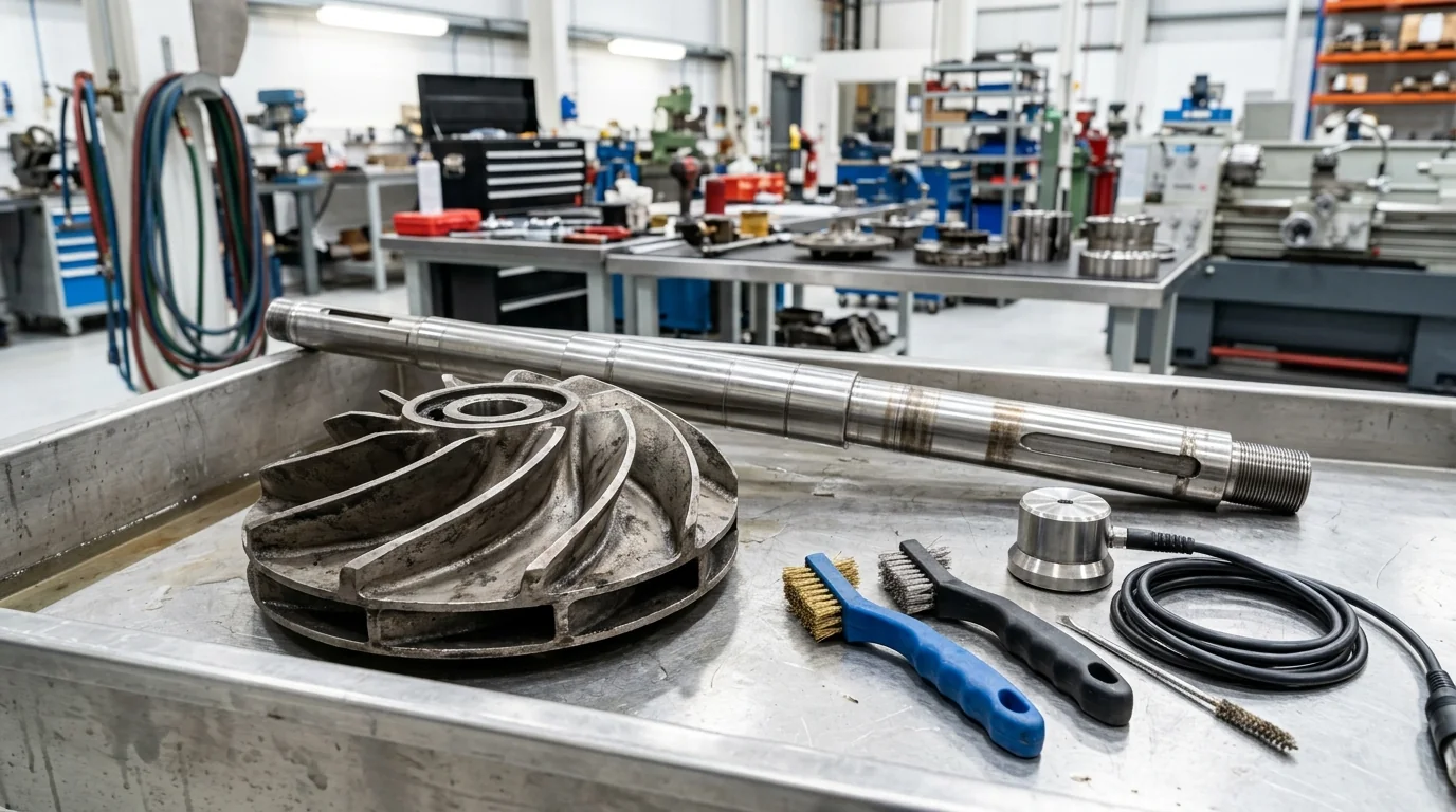
Hot Oil Pump Coking: Root Causes, Carbon Deposit Removal & Systemic Prevention Manual
A definitive high-temperature pump maintenance guide, chemical descaling standard, and carbon deposit prevention manual for plant managers, utility superintendents, and process engineers across Narol, Vatva GIDC, Odhav, Surat, and Gujarat.
Quick Answer
In the continuous textile stenter drying houses, dye intermediate synthesis reactors, multi-daylight laminate pressing plants, and bitumen handling terminals of Gujarat and India—spanning Ahmedabad (Narol, Vatva GIDC, Odhav), Surat, Ankleshwar, and Dahej—hot oil circulation pumps handle organic heat transfer fluids at operating bulk temperatures between 250°C and 340°C. Over extended operating campaigns, fluid degradation leads to the formation of hard, baked carbon deposits known as coke. When carbon deposits accumulate inside the centrifugal pump—coating the intermediate cooling bracket, packing the mechanical seal spring pocket, choking the throttle bush, and encrusting impeller passages—the pump suffers severe performance collapse: mechanical seal faces hang up and leak, bearing housing temperatures spike beyond 115°C, dynamic rotor unbalance triggers severe vibration (> 5.5 mm/s RMS), and flow rates drop by 20% - 40%. Resolving pump coking requires a rigorous engineering approach: diagnosing the chemical mechanisms (thermal cracking versus oxidation), executing safe on-site or workshop chemical descaling, reconditioning mechanical seals with monolithic direct-sintered silicon carbide faces, and installing system-level prevention systems including expansion tank nitrogen blanketing and side-stream filtration.
Key Takeaways
- Differentiate Thermal Cracking from Fluid Oxidation. Thermal cracking generates volatile light ends and solid carbon, while oxidation produces viscous acid sludge.
- Inspect Mechanical Seal Spring Pockets for Coke Hang-Up. Baked carbon encrustation prevents axial spring movement, causing face separation and leakage.
- Execute Multi-Stage Chemical Descaling SOPs. Use organic hydrocarbon flushing solvents followed by ultrasonic mechanical cleaning to remove baked coke.
- Install Expansion Tank Nitrogen Blanketing. Eliminating air contact at the expansion tank cuts fluid oxidation and coking by > 85%.
Introduction
Across Gujarat's vibrant manufacturing landscape—from the textile dyehouses and stenter drying ranges of Narol and Surat to the chemical synthesis reactor blocks of Vatva GIDC, Odhav, Ankleshwar, and Dahej—thermic fluid pumps circulate high-temperature heat transfer media up to 350°C without requiring high system pressure.
However, continuous exposure to extreme heat, air ingress, and localized hotspots inevitably causes chemical breakdown of organic heat transfer fluids:
- The Oxidation Hazard: When hot thermal fluid in the expansion tank contacts atmospheric oxygen, it oxidizes into acidic sludge, resins, and carbon particles.
- The Thermal Cracking Crisis: When fluid flow is throttled or the pump is shut down while furnace refractory remains hot, oil temperatures exceed the fluid's thermal cracking threshold (> 360°C), snapping hydrocarbon bonds into volatile light ends and solid carbon residue (coke).
- The Mechanical Consequence: Hard carbon residue migrates through the system, depositing inside the narrow clearances of the circulation pump. It packs the mechanical seal spring pockets, freezes throttle bushings, creates unbalance on the impeller, and destroys bearing lubrication.
- The Engineering Standard: Following ISO 5199, ISO 2858, and DIN 24255 standards—incorporating periodic chemical flushing, ultrasonic mechanical descaling, dynamic balancing to Grade G2.5, and nitrogen expansion tank blanketing—guarantees clean internal flow passages and maximum pump longevity.
2. Master Thermal Fluid Degradation & Coking Characteristic Matrix
Review the chemical mechanisms, physical properties, and pump damage modes associated with thermal fluid degradation:
| Degradation Mechanism | Chemical Trigger Condition | Typical Laboratory Indicators | Primary Pump Mechanical Impact |
|---|---|---|---|
| 1. Thermal Cracking (Overheating) | Film temp > 360°C (refractory soak) | High light ends, low flash point, CCR > 1.0% | Hard, brittle coke crusts; seal face hang-up |
| 2. Fluid Oxidation (Air Ingress) | Hot oil (> 60°C) contacting air | High Total Acid Number (TAN > 1.0), viscosity surge | Sticky, black asphaltic tar sludge; fin choking |
| 3. Contamination (Water/Chemicals) | Process leakage or condensation | Moisture > 500 ppm, low boiling point | Steam cavitation hammering; seal face fracturing |
| 4. Low-Velocity Boundary Layer | Flow velocity < 1.5 m/s in coils | Localized hot spots; high ΔT across heater | Volute cutwater carbon scaling; flow collapse |
3. The Chemical Physics, Oxidation Kinetics & Thermal Cracking Math
Thermal Cracking vs Oxidation Reaction Kinetics (k = A · e^-E_a/RT)
The rate of thermal degradation doubles for every 10°C increase in film temperature above the fluid's maximum recommended boundary limit per the Arrhenius reaction rate equation:
Interactive Engineering Hydraulic Sizer
Live ISO 5199 / API 610 Dynamic Engine- At 300°C, a high-quality synthetic fluid has a degradation rate factor k_1.
- If fluid stagnates in the pump seal chamber and heats to 330°C (ΔT = +30°C):
Conradson Carbon Residue (CCR) & Pentane Insoluble Metrics
Thermal fluid condition is monitored through laboratory analysis of carbon-forming potential:
- Conradson Carbon Residue (CCR): Fresh oil exhibits CCR < 0.05 wt%. When CCR exceeds 1.0 wt%, solid carbon precipitation accelerates rapidly.
- Pentane / Toluene Insolubles: High concentrations of pentane insolubles (> 0.5%) indicate suspended abrasive carbon grit that scours pump wear rings and mechanical seal faces.
Boundary Layer Stagnation Film Temperature Math (T_film = T_bulk + [q''] / [h])
Heat flux across pump casing walls and heater tubes creates a thermal boundary layer:
Where:
- q''_flux is the heat flux (W/m²).
- h_conv is the fluid convective heat transfer coefficient.
- If fluid velocity drops, h_conv decreases, causing the localized film temperature (T_film) to spike past 370°C, instantly baking fluid molecules into coke against hot metal surfaces.
Carbon Deposit Thermal Insulating Resistance Math (R_th = (t_coke) / (k_coke))
Baked carbon acts as an effective thermal insulator (k_coke ≈ 0.2 W/m\cdotK compared to ductile iron k_iron ≈ 36 W/m\cdotK):
- A thin 1.0 mm layer of coke inside the intermediate throttle bracket reduces heat dissipation to the cooling fins by over 80%, driving conducted shaft heat directly into the drive-end bearings.
Rotor Mass Eccentricity & Coking Dynamic Unbalance Force (F_unbalance = m · e · ω²)
When carbon sludge accumulates unevenly inside the rotating impeller vanes:
- Just 15 grams of asymmetric carbon buildup at an impeller radius of 125 mm operating at 2900 RPM generates an unbalance dynamic centrifugal force of over 170 Newtons, inducing violent 1X vibration (> 6.0 mm/s RMS) and accelerating fatigue failure of bearings and shaft sleeves.
4. The 7 Primary Symptoms & Root Causes of Hot Oil Pump Coking
Symptom 1: Mechanical Seal Spring Pocket Packout & Face Hang-Up
- Mechanism: Carbon particles migrate into the mechanical seal cartridge, compacting inside the wave spring or multiple coil springs.
- Consequence: The flexible seal face is locked in place, unable to compensate for axial shaft thermal movement. Seal faces separate, causing continuous hot oil leakage.
- Fix: Strip cartridge seal, ultrasonically descale in solvent, and install protected stationary spring mechanical seals conforming to API 682.
Symptom 2: Intermediate Throttle Bushing Clearance Choking
- Mechanism: Carbon sludge bakes inside the narrow diametrical clearance (0.25 - 0.35 mm) of the long intermediate throttle bush.
- Consequence: Throttle bush clearance chokes completely, restricting thermal fluid exchange and creating severe shaft friction drag.
- Fix: Re-machine throttle bush bore to OEM clearance; chemically flush cooling bracket cavity.
Symptom 3: Impeller Vane Passage Encrustation & Flow Collapse
- Mechanism: Carbon scabs adhere to the inner curved surfaces of closed impeller shroud plates and volute cutwater.
- Consequence: Hydraulic friction increases dramatically, narrowing flow passages and causing a 15% - 30% drop in delivered pump flow and discharge head.
- Fix: Mechanically scrape, glass bead blast, and dynamically balance impeller to ISO 5199 Grade G2.5.
Symptom 4: Plan 62 Quench Chamber Vapor Oxidation & Smoking
- Mechanism: Small amounts of high-temperature vapor leaking past the primary seal face contact atmospheric oxygen in an unquenched chamber.
- Consequence: Vapors instantly oxidize into black smoke, carbonizing on the atmospheric side of the seal sleeve.
- Fix: Maintain continuous nitrogen, steam, or synthetic high-temp fluid quench in the Plan 62 auxiliary port.
Symptom 5: High 1X / 2X Dynamic Vibration from Asymmetric Carbon Clots
- Mechanism: Irregular lumps of carbon break free and lodge in some impeller vanes while others remain clean.
- Consequence: Significant mass eccentricity creates severe 1X rotational vibration harmonics and high bearing load.
- Fix: Complete rotor strip-down, chemical cleaning, and precision dual-plane dynamic balancing on an electronic balancing machine.
Symptom 6: Bearing Housing Thermal Soak & Grease Carbonization
- Mechanism: Insulating coke layers inside the bracket prevent convective heat dissipation across cooling fins.
- Consequence: Conducted heat raises bearing skin temperatures above 115°C, carbonizing bearing grease into black grit and causing ball skidding.
- Fix: Descale bracket internal walls, install new C3 radial internal clearance bearings, and lubricate with synthetic polyurea grease.
Symptom 7: Rapid Catastrophic Seal Leakage & Spray Fire Hazard
- Mechanism: Hard carbon particles become trapped between the narrow (0.5 µm) sealing interface of the primary faces.
- Consequence: Abrasive three-body wear scores deep circular grooves into carbon or silicon carbide faces, leading to sudden spray leakage.
- Fix: Install monolithic direct-sintered SSiC vs SSiC running faces with flexible Grafoil secondary packing rings.
5. Step-by-Step Chemical Descaling & Mechanical Carbon Removal SOPs
Execute this structured engineering protocol when cleaning and restoring a coked thermic fluid pump:
Phase 1: In-Situ System Solvent Flush & Circulation SOP
- Chemical Flush Addition: Dose the operating thermal loop with a specialized hydrocarbon-based chemical cleaning solvent (5% - 10% concentration) while operating at 120°C - 150°C.
- Circulation Duration: Circulate solvent for 24 to 48 hours to dissolve soft sludge and loosen baked carbon deposits across piping and pump volutes.
- System Draining: Drain contaminated fluid completely while hot (> 80°C) to ensure suspended carbon particles are purged from low-point drain headers.
Phase 2: Pump Dismantling & Component Carbon Inspection SOP
- Back Pull-Out Extraction: Isolate pump, drain casing, and extract the back pull-out rotating assembly to the clean workshop bench.
- Visual Inspection: Inspect impeller vanes, wear rings, intermediate bracket cooling channels, and mechanical seal cartridge for carbon thickness and pitting.
Phase 3: Ultrasonic Alkaline & Hydrocarbon Bath Descaling SOP
- Solvent Immersion: Submerge disassembled metallic components (impeller, shaft sleeve, seal gland, bracket) in an ultrasonic cleaning tank filled with high-flash-point hydrocarbon solvent heated to 60°C.
- Ultrasonic Cavitation: Run ultrasonic agitation for 60 to 90 minutes to break down hard, baked coke crusts from internal spring pockets and blind holes.
- Manual Finishing: Use non-abrasive brass scrapers and scotch-brite pads to clean critical gasket faces and O-ring grooves. Zero wire brushes on machined sealing faces.
Phase 4: Mechanical Seal Lapping & SSiC Face Restoration SOP
- Flatness Inspection: Inspect monolithic silicon carbide seal faces using monochromatic light and optical flat.
- Precision Lapping: Lap seal faces on a diamond lapping table to achieve flatness within < 2 light bands (0.6 µm) and surface finish R_a < 0.05 µm.
- Spring Pack Renewal: Replace carbon-packed wave springs with new high-tensile Inconel X-750 springs.
Phase 5: Dynamic Rotor Balancing to ISO 5199 Grade G2.5 SOP
- Balancing Run: Mount the cleaned impeller, shaft, and keys onto an electronic dynamic balancing machine.
- Correction Limits: Achieve residual unbalance < 1.0 g\cdotmm/kg conforming to ISO 5199 Grade G2.5. Document final residual unbalance per plane on balancing certificate.
Phase 6: Reassembly, Laser Hot Alignment & Nitrogen Commissioning SOP
- C3 Bearing Installation: Install new high-temperature C3 radial internal clearance bearings lubricated with synthetic polyurea grease.
- Laser Hot Alignment: Assemble pump skid, perform cold alignment with vertical growth offset (+0.25 mm), and verify alignment hot at 280°C (offset < 0.03 mm).
- Nitrogen Purge: Blanket the expansion tank with dry nitrogen gas at 0.2 - 0.5 bar to permanently eliminate atmospheric oxygen contact.
6. Materials of Construction, Metallurgy & High-Temperature Sealing
Nodular Ductile Iron (GGG 40.3) & Cast Carbon Steel (ASTM A216 WCB)
- Pressure Containment: High-temperature Nodular Ductile Iron (EN-GJS-400-18-LT / GGG 40.3) or Cast Carbon Steel (ASTM A216 WCB) casings capable of withstanding thermal shock and 16 bar working pressure up to 350°C.
Monolithic Direct-Sintered Silicon Carbide (SSiC) Seal Faces
- Mechanical Seal Faces: Solid direct-sintered silicon carbide (SSiC) running against SSiC or Tungsten Carbide faces with flexible Grafoil or FFKM secondary O-rings.
High-Purity Flexible Grafoil Gaskets & Secondary O-Rings
- Casing Sealing: Pure flexible exfoliated graphite (Grafoil) die-formed rings and SS316 spiral-wound gaskets with flexible graphite filler for leak-tight casing joints at 350°C.
Precision Balanced SS316 & High-Tensile Carbon Steel Rotors
- Rotating Shafts: Precision ground High-Tensile Carbon Steel or SS410 martensitic stainless steel shafts sleeved with SS316 to eliminate corrosion under packing rings.
7. The Utility Engineer's Coking Remediation & Prevention Decision Matrix
Follow this structured engineering framework when determining corrective actions for coked pumps:
| Observed Coking Severity | Fluid Carbon Metric (CCR) | Recommended Remediation Action | Expected Turnaround Time |
|---|---|---|---|
| Light Sludge / Discolored Oil | CCR < 0.5 wt%, TAN < 0.5 | Side-stream micron filtration + Nitrogen blanketing | 12 to 24 hours on-site |
| Seal Leaking / Springs Coked | CCR = 0.5% - 1.0 wt% | Workshop seal ultrasonic descaling + face lapping | 24 to 48 hours workshop |
| High Vibration / Flow Drop > 20% | CCR > 1.0 wt%, High Insolubles | Full system solvent flush + Dynamic rotor balancing | 3 to 4 working days |
| Severe Carbon Solidification | Fluid gelatinized / burnt black | Complete fluid replacement + Complete pump overhaul | 4 to 6 working days |
8. Worked Gujarat Textile, Chemical & Processing Mill Case Studies
Case 1: Narol Textile Dyeing Stenter Hot Oil Pump Coking Overhaul
- Plant Context: A continuous cotton fabric dyeing and stenter finishing mill in Narol operating a 100 m³/h, 4.5 bar thermic fluid pump circulating mineral oil at 285°C.
- Problem: Mechanical seal failed catastrophically every 4 to 6 weeks; carbon crust packed the seal spring pocket; bearing skin temperature reached 122°C.
- Root Cause: Open expansion tank vent allowed hot oil (> 75°C) to oxidize with atmospheric air, increasing CCR to 1.42 wt%. Carbon sludge fouled intermediate bracket cooling fins.
- Action Plan: Teflow Pumps emergency field team:
- Dosed loop with chemical flushing solvent and drained oxidized fluid. - Overhauled pump; ultrasonically descaled mechanical seal; lapped monolithic SSiC faces. - Dynamically balanced impeller to ISO 5199 Grade G2.5. - Installed a nitrogen blanketing kit (0.3 bar) on the expansion tank.
- Outcome: Zero coking incidents over 22 consecutive operating months; bearing temperature stabilized at 76°C; seal life extended > 4×.
Case 2: Vatva GIDC Dye Reactor Thermal Oil Pump Chemical Descaling
- Plant Context: An azo dye synthesis plant in Vatva GIDC operating a 60 m³/h hot oil pump at 310°C.
- Problem: Pump flow rate collapsed from 60 m³/h down to 38 m³/h due to thick carbon scaling inside the impeller channels.
- Action Plan: Extracted back pull-out assembly to our Ahmedabad workshop; glass bead blasted impeller vanes; machined throttle bush to OEM clearance; balanced rotor to Grade G2.5.
- Outcome: Delivered full 60 m³/h flow at rated pressure; reactor batch heating time reduced by 28%.
Case 3: Surat Synthetic Weaving Thermic Fluid Pump Carbon Removal
- Plant Context: A polyester yarn processing mill in Surat operating dual thermic fluid pumps (270°C).
- Problem: High 1X vibration (6.2 mm/s RMS) caused repeated coupling pin destruction.
- Action Plan: Removed 22 grams of hardened carbon cake from two impeller vanes; precision balanced rotating element on electronic dynamic balancing rig.
- Outcome: Vibration velocity reduced to 0.85 mm/s RMS (ISO 5199 Zone A).
Case 4: Odhav Industrial Estate Multi-Daylight Press Carbon Flush
- Plant Context: A decorative laminate pressing facility in Odhav operating hot oil platens at 220°C.
- Problem: Platen temperature unevenness caused by carbon sludge choking pump discharge throttle lines.
- Action Plan: Executed 36-hour chemical solvent flush and cleaned pump casing volute cutwater.
- Outcome: Platen temperature variance reduced from ± 18°C to ± 2.5°C.
Case 5: Ankleshwar GIDC Specialty Chemical Hot Oil Loop Recovery
- Plant Context: A pharmaceutical intermediate facility in Ankleshwar GIDC operating at 300°C.
- Problem: Chronic seal smoke and carbon buildup in Plan 62 quench port.
- Action Plan: Converted quench to pressurized nitrogen barrier and lapped silicon carbide seal faces.
- Outcome: 100% emission-free operation; zero quench carbonization.
Case 6: Dahej PCPIR Petrochemical Terminal Heat Transfer Reconditioning
- Plant Context: A chemical terminal in Dahej PCPIR operating high-flow BB1 split-case hot oil pumps.
- Problem: Hard carbon scale on shaft sleeves scored throat bushings.
- Action Plan: Replaced shaft sleeves with hard-coated SS316 sleeves; fitted Grafoil packing rings.
- Outcome: Restored full sealing integrity; zero weeping.
9. Comprehensive Master Hot Oil Pump Coking Prevention Checklist
Execute this maintenance verification protocol to eliminate pump coking and ensure high-temperature reliability:
Hot Oil Pump Coking Prevention & System Maintenance Protocol
10. Summary & Specialized Hot Oil Pump Overhaul Services in Gujarat & India
Resolving hot oil pump coking—diagnosing thermal cracking and oxidation kinetics, executing precision chemical descaling, reconditioning mechanical seals with monolithic direct-sintered silicon carbide faces, dynamically balancing rotating assemblies to ISO 5199 Grade G2.5, and blanketing expansion tanks with nitrogen across Narol, Vatva GIDC, Odhav, Surat, Ankleshwar, and Dahej—conforming to ISO 5199, ISO 2858, and DIN 24255 standards—is the proven engineering standard for high-temperature reliability.
Partnering directly with an established Gujarat rotating machinery manufacturer provides textile mill managers, utility superintendents, and process engineers with immediate technical access to on-site chemical cleaning teams, ultrasonic descaling tanks, precision diamond lapping tables, dynamic balancing facilities, and genuine spares dispatched directly from our Ahmedabad factory. Our technical engineers provide emergency on-site troubleshooting, turnkey pump overhauls, and complete thermal loop audits.
Teflow Pumps operates a specialized industrial machinery manufacturing and service facility in Ahmedabad, providing emergency thermic fluid pump overhauls, high-temperature mechanical seal replacements, precision dynamic balancing, laser alignment, custom impeller casting, and genuine rotating equipment spares across Gujarat and India conforming to ISO 5199, ISO 2858, DIN 24255, and IS 5120 standards.
- Direct Technical & Emergency Helpline: +91 98251 62709
- WhatsApp Technical Desk: Share thermal fluid lab reports (CCR, TAN, viscosity), pump nameplate photos, coked seal photos, or vibration readings to wa.me/919825162709 for immediate technical review, coking diagnosis, and formal quotation.
- Request an On-Site Hot Oil Pump Coking & Overhaul Audit: Contact our senior rotating equipment engineers for emergency plant surveys, chemical descaling proposals, and formal quotation. Our engineering team conducts comprehensive thermal evaluations, verifies ISO 5199 criteria, provides precision on-site or workshop reconditioning, and dynamically balances overhauled hot oil pumps to ensure maximum uptime across Gujarat's textile and chemical processing mills. We provide rapid technical evaluations, on-site plant surveys, and formal quotes.