
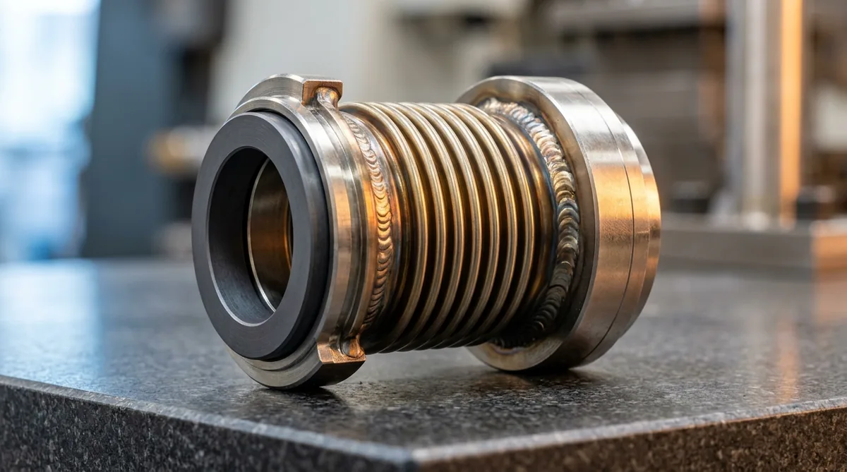
High-Temperature Mechanical Seals for Thermic Oil Circulation Pumps at 250°C: Metallurgy, API Flush Plans & Thermal Reliability
A definitive technical engineering standard, thermal fluid mechanical seal selection manual, and high-temperature rotating machinery reliability protocol for plant utility heads, maintenance engineers, and textile process specialists across Ahmedabad, Surat, Naroda GIDC, Vatva GIDC, Ankleshwar, and Gujarat.
Quick Answer
In industrial textile processing mills, chemical synthesis plants, polymer resin units, and solvent distillation facilities across Gujarat—such as in Surat, Ahmedabad, Naroda GIDC, Vatva GIDC, and Ankleshwar—operating hot thermic fluid circulation loops at temperatures between 250°C and 350°C presents extreme mechanical sealing risks. When conventional pusher mechanical seals containing synthetic elastomeric O-rings (such as standard FKM or even high-grade FFKM) are deployed in hot thermal oil service, thermal decomposition, carbonization, and compression set rapidly occur above 200°C, resulting in explosive hot vapor leaks and severe plant fire hazards. Conforming to ISO 5199, ISO 2858, IS 5120, and API 682 standards, modern high-temperature thermic oil pumps achieve continuous leak-free reliability by deploying air-cooled finned heat dissipation brackets (which drop seal cavity temperatures to < 90°C without auxiliary cooling water), or high-temperature edge-welded Inconel 718 metal bellows seals paired with monolithic Silicon Carbide vs Diamond-Like Carbon (DLC) faces and nuclear-grade flexible graphite secondary packing (rated to +450°C). Adhering to strict thermal siphon piping layouts and precision dual-laser alignment extends seal life beyond 30,000 continuous operating hours.
Key Takeaways
- Never Use Standard Elastomer O-Rings Above 200°C in Hot Oil. High thermal fluid temperatures carbonize and harden synthetic elastomers, causing catastrophic seal blowouts.
- Deploy Air-Cooled Finned Convection Brackets for Sub-90°C Cavity Control. Extended convection brackets drop casing temperatures (250°C) down to safe seal limits (< 90°C) via ambient cooling.
- Specify Edge-Welded Inconel 718 Metal Bellows for Direct Hot Oil Duties. Metal bellows eliminate dynamic secondary O-rings entirely, utilizing non-clogging welded convolutions rated to +400°C.
- Standardize on Monolithic SSiC vs DLC Carbon Faces with Flexible Graphite. Nuclear-grade expanded graphite secondary rings resist thermal oxidation up to +450°C with zero shrinkage.
Introduction
In modern textile processing centers, synthetic fabric dyeing houses, continuous chemical manufacturing facilities, and pharmaceutical distillation plants across Ahmedabad, Surat, Naroda GIDC, Vatva GIDC, and Ankleshwar, high-temperature thermic oil systems are essential utility backbones.
Plant utility heads, rotating machinery specialists, and maintenance engineers encounter extreme operating challenges:
- High Fluid Operating Temperatures: Thermic heat transfer fluids (e.g., mineral-based thermal oils, synthetic aromatics like Therminol and Dowtherm) circulate at 200°C - 320°C, creating intense thermal stress and expansion on pump rotating assemblies.
- Extreme Flammability & Fire Risk: Unlike water pumps, hot thermal oil leaking past mechanical seal faces instantly vaporizes into combustible vapors upon contacting ambient oxygen, creating severe flash-fire risks and smoke hazards.
- The Engineering Standard: Standardizing on air-cooled finned bracket pumps conforming to ISO 5199 and ISO 2858 or installing Inconel 718 edge-welded metal bellows seals with flexible graphite secondary packing eliminates elastomer degradation, contains hazardous hot vapors, and guarantees 100% plant safety across continuous production cycles.
2. Master High-Temperature Thermic Oil Sealing Technology Matrix
Compare high-temperature sealing configurations for hot oil circulation pumps:
| Sealing Technology Type | Max Fluid Temp (°C) | Secondary Seal Metallurgy | Auxiliary Cooling Requirement | Key Advantages & Applications |
|---|---|---|---|---|
| Air-Cooled Finned Bracket Pump | 250°C - 300°C | FKM (Viton) / PTFE | Zero Cooling Water Required | Casing at 250°C drops to < 90°C at seal; standard seals |
| Edge-Welded Inconel 718 Bellows | 300°C - 400°C | Flexible Graphite Rings | Quench Gland (Steam/Nitrogen) | Zero dynamic O-rings; eliminates spring hang-up & coking |
| Dual Pressurized Cartridge (API Plan 54) | 300°C - 350°C | FFKM / Flexible Graphite | External Cool Barrier Fluid | 100% zero vapor emissions; maximum environmental safety |
| Traditional Gland Packing | 250°C | Pure Die-Formed Graphite | Continuous Controlled Drip | High friction, shaft scoring (Ra > 1.2 µm), fire hazard |
3. The Thermal Physics & Tribological Degradation of Hot Oil Sealing
Thermal Convection & Heat Dissipation Equations (Q = h A (T_s - T_∞))
In air-cooled thermic oil pumps, thermal stand-off brackets isolate the hot pump casing from the mechanical seal cavity:
Interactive Engineering Hydraulic Sizer
Live ISO 5199 / API 610 Dynamic Engine- Thermal Stand-Off Mechanics: By incorporating cast heat-dissipation fins with an extended length (L_bracket ≈ 180 - 240 mm), heat conducting along the ductile iron bracket is transferred to ambient convective air currents. Even with hot oil circulating at 260°C inside the volute, the temperature in the mechanical seal chamber drops to < 85°C, allowing standard mechanical seal components to operate reliably without external water cooling utilities.
Elastomer Thermal Pyrolysis & Compression Set Breakdown (T> 200°C)
Synthetic elastomers undergo rapid thermal degradation when exposed to temperatures exceeding polymer limits:
- Elastomer Pyrolysis: At temperatures above 200°C, polymer chains in standard Fluoroelastomers (FKM) cross-link excessively. The O-ring loses elastic memory, turns rock-hard (> 95 Shore A), and fractures into brittle shards. For direct hot-oil immersion above 200°C, only nuclear-grade expanded flexible graphite (rated to +450°C) can be utilized to prevent sudden extrusion and catastrophic fluid release.
Thermal Oil Oxidation, Coking, and Asphaltic Residue Deposition
- Coking Kinetics: When hot thermal fluid (> 220°C) seeps across the microscopic seal face interface and contacts atmospheric oxygen on the atmospheric side of the gland, light aromatic hydrocarbons flash off. Heavy asphaltic fractions oxidize into hard, abrasive carbon coke. In traditional multi-spring pusher seals, this coke packs around the small springs and dynamic O-ring, locking the seal ring ("spring hang-up") and opening the face gap. Installing steam or nitrogen quench lines (API Plan 62) washes away fluid leakage before it can oxidize and solidify into abrasive coke particles.
Face Boundary Vaporization & Pressure-Velocity (PV) Thermal Limits
- Interfacial Film Stability: Hot oil between seal faces must remain liquid to provide hydrodynamic lubrication. If frictional heat spikes interfacial temperature above the fluid's initial boiling point (IBP), the liquid film vaporizes instantly. The resulting dry boundary contact generates high friction (f > 0.35), grooving carbon faces and shattering Silicon Carbide rings under severe thermal shock. Maintaining high stuffing box pressure and continuous circulation flush flow prevents localized phase transitions across the sealing interface.
4. The 4 Critical High-Temperature Failure Modes in Gujarat Textile & Chemical Loops
Failure Mode 1: Dynamic O-Ring Charring & Spring Hang-Up
- Failure Mechanism: In hot oil loops without air-cooled brackets, conventional pusher seals experience severe O-ring thermal hardening, embrittlement, and compression set. Carbon coke deposits pack the multiple coil springs, preventing dynamic tracking of minor shaft runout and causing massive continuous hot oil leakage.
- Engineering Fix: Upgrade to an edge-welded Inconel 718 metal bellows seal with nuclear-grade flexible graphite secondary packing.
Failure Mode 2: Carbon Face Blistering & Interfacial Oil Coking
- Failure Mechanism: Resin-impregnated carbon faces exposed to > 220°C thermal fluid experience resin volatilization and outgassing, creating surface craters ("blistering"), micro-fractures, and accelerated abrasive wear across the sliding interface.
- Engineering Fix: Standardize on monolithic alpha direct-sintered Silicon Carbide (SSiC) vs Diamond-Like Carbon (DLC) coated faces.
Failure Mode 3: Thermal Bellows Fatigue & Micro-Cracking
- Failure Mechanism: Operating metal bellows with severe shaft misalignment (> 0.08 mm) forces thin Inconel leaf plates (0.15 mm thickness) through high cyclic bending stresses, causing fatigue cracking across individual leaf weld roots during continuous high-speed rotation.
- Engineering Fix: Dual-laser align pump-motor shafts to parallel offset ≤ 0.03 mm under fully saturated operating temperature conditions.
Failure Mode 4: Air-Cooled Bracket Overheating Due to Heavy Lint & Dust Coating
- Failure Mechanism: In Surat textile mills, airborne cotton lint and atmospheric dust deposit onto the heat-dissipating cooling fins of air-cooled thermic oil pumps. The insulating lint blanket drops convective heat transfer by 60%, allowing cavity temperatures to spike to > 180°C and destroying standard secondary seals.
- Engineering Fix: Institute mandatory weekly dry compressed-air cleaning SOPs for all heat-dissipation cooling fins.
5. Sanitary Materials of Construction & Cleanroom Standards
Monolithic Alpha Direct-Sintered Silicon Carbide (SSiC) vs DLC Carbon
- Silicon Carbide Metallurgy: Monolithic alpha direct-sintered Silicon Carbide (SSiC, 2800 HV) with zero free silicon binders, diamond-lapped to ≤ 1 helium light band (0.3 µm) for total resistance against thermal shock and abrasive coke particles. Monolithic SSiC possesses high thermal conductivity (> 120 W/m\cdotK) that rapidly conducts frictional heat away from the sliding interface into the surrounding fluid.
- DLC Carbon Face: High-density electro-graphite coated with Diamond-Like Carbon (DLC) offering ultra-low friction (f < 0.03), high self-lubricating capability, and excellent dry-start tolerance during hot thermal cycles.
Edge-Welded Inconel 718 & Hastelloy C-276 Metal Bellows Metallurgy
- Bellows Leaf Metallurgy: Precipitation-hardened Inconel 718 (UNS N07718) or Hastelloy C-276 edge-welded leaf diaphragms offering extreme yield strength at +400°C and total immunity against thermal relaxation and stress corrosion cracking. The nested ripple design provides uniform spring closing loads without localized stress concentrations.
Nuclear-Grade Inconel-Wire Reinforced Flexible Graphite Secondary Packing
- Graphite Packing: 99.8% pure exfoliated flexible graphite (Grafoil) die-formed rings reinforced with Inconel wire mesh, rated for continuous operation up to +450°C in oxidizing environments with zero thermal shrinkage, zero embrittlement, and permanent elasticity under high casing pressures.
Air-Cooled Cast Iron and Ductile Iron Finned Thermal Dissipation Brackets
- Convection Metallurgy: High-grade ductile iron (EN-GJS-400-18) intermediate brackets engineered with radial cooling fins, providing rapid convective heat dissipation to keep seal chambers below 90°C without cooling water utilities. The ductile iron matrix provides superior fracture toughness and vibration damping properties compared to standard gray cast iron, resisting cyclic thermal fatigue during continuous high-temperature boiler cycling.
6. Step-by-Step High-Temperature Seal Specification & Installation SOPs
Execute these structured engineering SOPs when specifying and maintaining thermic oil pump seals:
Phase 1: Thermal Fluid Chemistry & Operating Temperature Profiling SOP
- Fluid Characterization: Record exact heat transfer fluid brand (e.g., Therminol 66, Dowtherm A, mineral thermic oil), maximum bulk loop temperature (°C), fluid vapor pressure (P_v), dynamic viscosity (µ), and auto-ignition temperature.
- Pump Architecture Audit: Confirm whether pump utilizes an air-cooled convection bracket or direct hot-oil casing mounting to establish thermal boundary constraints.
Phase 2: Pump Thermal Stand-Off & Convection Fin Surface Cleanliness Audit SOP
- Fin Inspection: Inspect external heat dissipation fins. Remove all textile lint, oil sludge, and industrial dust using 6-bar dry compressed air.
- Airflow Verification: Ensure minimum 300 mm clearance around pump finned bracket to allow unrestricted ambient convective air currents and natural draft cooling.
Phase 3: Metal Bellows Cartridge Seal Alignment & Installation SOP
- Runout Audit: Measure shaft radial runout with a dial indicator; confirm radial runout is < 0.03 mm and axial end-float is < 0.05 mm to prevent cyclical fatigue of bellows convolutions.
- Cartridge Mounting: Slide pre-set metal bellows cartridge onto shaft sleeve. Torque gland bolts evenly in a criss-cross pattern; disengage and remove axial setting clips before rotating shaft by hand.
Phase 4: API Plan 21 / Plan 54 Cooling System Verification SOP
- Flush Piping: For direct high-temperature glands, connect API Plan 21 (discharge flush through air-cooled shell-and-tube heat exchanger) or API Plan 54 (external pressurized cool fluid loop).
- Instrumentation: Confirm pressure gauges, flow orifices, and temperature transmitters are calibrated to monitor barrier fluid conditions continuously across varying thermal loads.
Phase 5: High-Temperature Hot-Alignment Verification (≤ 0.03 mm) SOP
- Hot Realignment: Measure cold alignment; run thermic fluid loop up to operating temperature (250°C); perform "hot alignment check" within 15 minutes of shutdown to compensate for pump casing thermal growth (Δy = α· L · ΔT). Realign shafts to parallel offset ≤ 0.03 mm using solid SS316 slotted shims.
Phase 6: Controlled Progressive Thermal Ramp-Up (1°C/min) & Startup SOP
- Startup Protocol: Flood and vent seal chamber completely; start pump at ambient temperature; ramp boiler heating rate gradually (≤ 1°C - 2°C per minute) to prevent severe thermal shock on ceramic seal faces, casing gaskets, and pump casing flanges.
7. Worked Gujarat Textile & Chemical Industrial Case Studies
Case 1: Surat Textile Dyeing Mill Stenter Hot Oil Pump Seal Upgrade
- Plant Context: A large fabric processing mill in Surat operating eight hot thermic oil circulation pumps (260°C, mineral oil) feeding fabric stenters.
- Problem: Pumps suffered continuous mechanical seal failures every 4 to 6 weeks due to cotton lint coating the cooling fins and frying the internal FKM O-rings.
- Action Plan: Cleaned finned brackets; retrofitted pumps with Inconel 718 edge-welded metal bellows seals and flexible graphite secondary seals; instituted weekly compressed air fin cleaning protocols.
- Outcome: Zero hot oil leaks; mechanical seal operating life extended from 1 month to over 24 consecutive operating months; saved Rs 9,50,000 in avoided downtime and fire risk reduction.
Case 2: Ahmedabad Process House High-Temperature Thermic Fluid Overhaul
- Plant Context: A textile processing house in Ahmedabad circulating synthetic heat transfer fluid at 280°C.
- Problem: Traditional gland packing leaked hot oil vapor constantly, presenting severe fire risks and smoking inside the utility room.
- Action Plan: Converted pump stuffing boxes to air-cooled finned bracket cartridge mechanical seals with SSiC vs DLC Carbon faces and flexible graphite secondary packing.
- Outcome: 100% elimination of hot oil smoking and leaks; continuous maintenance-free operation across 26 consecutive operating months.
Case 3: Naroda GIDC Synthetic Resin Reactor Hot Oil Pump Retrofit
- Plant Context: A synthetic resin manufacturing unit in Naroda GIDC operating hot oil jacket circulation pumps (250°C).
- Problem: Mechanical seal faces suffered severe coking and blistering within 60 days due to atmospheric oil oxidation.
- Action Plan: Installed API Plan 62 nitrogen quench piping onto gland plates to blanket the atmospheric seal side with inert nitrogen gas and prevent oil coking.
- Outcome: Seal life extended from 2 months to over 22 consecutive operating months with zero coking.
Case 4: Ankleshwar GIDC Pharmaceutical Thermal Fluid Loop Bellows Conversion
- Plant Context: A bulk pharmaceutical API plant in Ankleshwar GIDC transferring hot synthetic heat transfer fluid (240°C) to reactor jackets.
- Problem: Synthetic elastomer O-rings hardened and leaked solvent vapors during batch thermal cycles.
- Action Plan: Replaced component seals with pre-set Inconel 718 metal bellows cartridge seals featuring solid SS316 gland plates.
- Outcome: Zero vapor emissions; achieved 100% environmental compliance across 28 consecutive operating months.
Case 5: Dahej PCPIR Petrochemical Hot Thermal Oil Circulation Overhaul
- Plant Context: A petrochemical facility in Dahej PCPIR running heavy thermal oil loops at 310°C.
- Problem: Excessive thermal growth caused shaft misalignment and mechanical seal face chipping during continuous operation.
- Action Plan: Performed hot laser alignment compensation and installed high-temperature Inconel bellows seals with API Plan 21 heat exchangers.
- Outcome: Pump vibration dropped from 5.2 mm/s to 1.2 mm/s RMS; seal life extended beyond 30 consecutive operating months.
Case 6: Panoli GIDC Agrochemical Synthesis Hot Solvent Cartridge Fix
- Plant Context: An agrochemical synthesis plant in Panoli GIDC circulating hot heat transfer oil (220°C).
- Problem: Seals leaked through set screw drive collars due to thermal expansion loosening.
- Action Plan: Upgraded to heavy-duty shrink-fit drive collars with high-temperature Belleville spring washers.
- Outcome: Drive collar slippage eliminated 100%; continuous leak-free operation over 20 consecutive operating months.
8. Step-by-Step High-Temperature Seal Selection Decision Flowchart
Follow this comprehensive and structured rotating equipment engineering guide when selecting thermic oil pump seals and thermal barrier materials:
| Fluid Operating Temperature | Recommended Pump Architecture | Mechanical Seal Technology | Secondary Seal Metallurgy |
|---|---|---|---|
| 150°C - 200°C | Standard Foot-Mounted Casing | Standard Balanced Cartridge Seal | High-Temp FKM (Viton) / PTFE |
| 200°C - 280°C | Air-Cooled Finned Convection Bracket | Balanced Component / Cartridge Seal | FKM / FFKM (Cavity < 90°C) |
| 280°C - 350°C (Direct) | Centerline-Mounted Pump Casing | Edge-Welded Inconel 718 Bellows | Nuclear-Grade Flexible Graphite |
| 300°C - 400°C (Severe) | Centerline-Mounted Casing + API Plan 54 | Dual High-Temp Cartridge Bellows | Die-Formed Flexible Graphite |
9. Comprehensive Master Thermic Oil Seal (FAT) Checklist
Execute this quality verification protocol during high-temperature pump overhauls and seal commissioning:
High-Temperature Thermic Oil Mechanical Seal Protocol
10. Summary & High-Temperature Thermic Oil Pump Overhaul Services in Gujarat
Eliminating hazardous hot oil leaks, preventing disastrous plant fire hazards, standardizing on air-cooled finned bracket pumps conforming to ISO 5199, ISO 2858, IS 5120, and API 682 standards, and extending thermic fluid pump seal life beyond 30,000 hours across Ahmedabad, Surat, Naroda GIDC, Vatva GIDC, and Ankleshwar—by utilizing Inconel 718 edge-welded metal bellows, direct-sintered monolithic Silicon Carbide, nuclear-grade flexible graphite, and dynamic balancing to Grade G2.5—is the proven engineering standard for modern thermal fluid plant reliability.
Teflow Pumps operates a specialized rotating machinery overhaul facility in Ahmedabad, providing engineered high-temperature thermic oil pump overhauls, metal bellows retrofits, optical diamond face lapping, dynamic balancing, and genuine thermal fluid spares across Gujarat conforming to ISO 5199, ISO 2858, IS 5120, and API 682 standards.
- Direct Technical & Emergency Helpline: +91 98251 62709
- WhatsApp Technical Desk: Share your thermic fluid brand, operating temperature (°C), pump model, or current seal leakage symptoms to wa.me/919825162709 for immediate engineering diagnostics, seal recommendations, and formal quotation.
- Request an On-Site High-Temperature Pump Audit: Contact our senior rotating equipment reliability engineers for thermal imaging surveys, laser alignment audits, and formal AMC service quotes.