
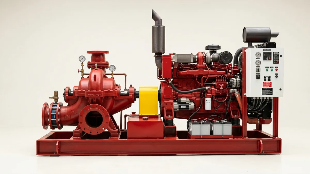
Failed NFPA Fire Pump Flow Test: Root Cause Diagnostics, Hydraulic Remediation & Repair Decision Path
A definitive fire protection system engineering manual, hydraulic failure diagnostic protocol, and repair versus overhaul decision guide for plant managers, HSE leads, and facility maintenance superintendents across Ahmedabad, Sanand, Changodar, Vatva GIDC, Dahej PCPIR, and Gujarat.
Quick Answer
In the large-scale manufacturing facilities, chemical process complexes, pharmaceutical parks, and hazardous warehousing hubs of Gujarat and India—spanning Ahmedabad (Sanand, Changodar, Vatva GIDC), Dahej PCPIR, Ankleshwar, and Hazira—maintaining a compliant fire protection water transfer pumping system is a strict statutory and insurance mandate. When an annual NFPA 25 (Standard for the Inspection, Testing, and Maintenance of Water-Based Fire Protection Systems) performance flow test fails, plant safety managers face an immediate crisis: insurance underwriters issue non-compliance notices, statutory factory inspectors demand immediate remediation, and the facility is left vulnerable to catastrophic fire loss. A failed test typically manifests in one of three hydraulic degradation modes: churn pressure falling > 5% below the original nameplate curve, rated 100% capacity head loss > 5%, or overload collapse where head drops below 65% of rated pressure at 150% flow. Resolving these failures requires a structured engineering decision path: differentiating between external testing errors (uncalibrated Pitot gauges, relief valve dumping, suction throttling) and internal mechanical degradation (enlarged wear ring clearances, impeller cavitation erosion, shaft misalignment, or diesel engine speed droop).
Key Takeaways
- Identify the Exact 3-Point Hydraulic Failure Mode. Determine whether head loss occurs at Churn (0%), Rated Flow (100%), or Overload (150%).
- Rule Out External Testing & Metering Errors First. Verify Pitot tube orifice sizing, hose nozzle condition, and relief valve seating before dismantling the pump.
- Inspect Impeller Wear Ring Radial Clearances. Clearances exceeding 2.0× original factory specifications cause massive internal recirculation and flow loss.
- Execute Structured Repair vs Overhaul Decision Path. Recondition minor clearances on-site or execute complete workshop overhaul with dynamic balancing.
Introduction
Across the major industrial manufacturing corridors of Gujarat—including Ahmedabad's automotive and engineering parks in Sanand, pharmaceutical belts in Changodar, chemical estates in Vatva GIDC, and the heavy petrochemical zones of Dahej PCPIR and Hazira—fire water transfer pump systems stand as the primary life-safety and asset-protection infrastructure.
When an annual NFPA 25 flow test fails, facility maintenance leads and safety officers face serious compliance and operational risks:
- The Regulatory and Insurance Crisis: Insurance risk engineers immediately suspend fire asset coverage or impose punitive insurance surcharges when flow testing reveals > 5% hydraulic degradation.
- The Diagnostic Dilemma: Many plants mistakenly replace expensive diesel engines or entire pump skids when the true root cause is simply worn wear rings, a weeping relief valve, or uncalibrated flow test orifices.
- The Engineering Standard: Following a rigorous engineering diagnostic path—evaluating hydraulic test curves against NFPA 20, NFPA 25, ISO 5199, IS 1520, and IS 5120 standards—allows plant teams to pinpoint the mechanical root cause, execute precision on-site or workshop reconditioning, and restore full certified flow capacity in minimum downtime.
2. Master NFPA 25 3-Point Flow Test Degradation Matrix
Review the 3 critical hydraulic test points, degradation thresholds, and diagnostic indicators governed by NFPA 25:
| Test Operating Condition | Target Hydraulic Boundary | Allowable Degradation Limit | Primary Mechanical Failure Indicators |
|---|---|---|---|
| 1. Churn Test (0% Flow) | 100% - 140% of rated net head | ≤ 5% drop from certified baseline | Wear ring leakage, PRV weeping, air ingress |
| 2. Rated Capacity (100% Flow) | 100% of rated net head | ≤ 5% drop from certified baseline | Impeller vane erosion, suction strainer blockage |
| 3. Peak Overload (150% Flow) | ≥ 65% of rated net head | Must maintain ≥ 65% head & speed | Driver speed droop, severe cavitation, cutwater wear |
3. The Mechanical Physics, Hydraulic Degradation Math & Calculations
NFPA 25 Hydraulic Acceptance Boundaries (Churn ≤ 140%, 100% Rated, 150% ≥ 65%)
During the annual NFPA 25 flow test, net differential head (H_net) is evaluated across 3 flow points:
Interactive Engineering Hydraulic Sizer
Live ISO 5199 / API 610 Dynamic Engine- Churn Point (Q = 0): Shutoff head must not exceed 140% of rated head (to protect system pipe fittings) and must not fall > 5% below the original factory test baseline.
- Rated Duty Point (Q = 100%): Net head must deliver ≥ 100% of rated nameplate head within a -5% allowable aging tolerance.
- Overload Point (Q = 150%): Net head must remain ≥ 65% of rated head, and driver power must not exceed maximum nameplate rating.
Pitot Tube Flow Orifice Discharge Equation (Q = 29.83 · c · d² · √(P))
Flow rate through standard playpipe hose nozzles is calculated using the NFPA Pitot orifice discharge formula:
Where:
- c is the nozzle discharge coefficient (0.97 for standard smooth bore playpipes).
- d is the internal nozzle diameter (1.75 in standard).
- P_pitot is the velocity pressure measured at the center of the stream in psi.
- Metric Conversion (Q_m³/h = Q_GPM · 0.2271): Verification of nozzle diameters (d) with digital vernier calipers is essential before declaring a pump failed, as nozzle tip erosion or burrs distort calculated flow rates by up to 15%.
Wear Ring Radial Clearance Enlargement & Recirculation Leakage Math
Internal leakage flow (Q_leak) across the impeller wear rings recirculates from high-pressure discharge back to the low-pressure suction eye:
- Doubling the wear ring clearance (Clr_diam from 0.30 mm to 0.60 mm) increases internal leakage flow by over 100%, causing a direct 6% - 12% loss in delivered pump flow and discharge head.
- When radial clearance exceeds 2.0× original OEM specification, the pump will inevitably fail its 100% and 150% NFPA flow test points.
Diesel Engine RPM Speed Droop vs Centrifugal Affinity Laws
Centrifugal pump performance is exponentially sensitive to driver rotational speed per the Affinity Laws:
- If a diesel engine governor droops by just 4% under heavy 150% overload load (e.g., dropping from 2900 RPM to 2784 RPM):
- This 7.84% head loss causes an otherwise healthy pump to fail NFPA 25 acceptance criteria purely due to engine fuel governor or turbocharger lag.
Suction Lift Air Ingress & NPSH Cavitation Head Loss
Air entrainment through loose gland packing or suction pipe flanges creates severe air binding:
- Even 2% entrained air by volume reduces centrifugal pump head by up to 10% and induces localized cavitation, causing rapid head collapse at high overload flow rates (150% Q).
4. The 7 Primary Root Causes of Fire Pump Flow Test Failures
Cause 1: Excessive Impeller Wear Ring Clearance (Internal Leakage)
- Mechanism: Abrasive silt in raw fire water storage reservoirs scours bronze wear rings, expanding diametrical clearances beyond 0.80 mm.
- Diagnostic Symptom: Severe head loss across all 3 test points, most pronounced at 100% and 150% flow.
- Fix: Machine and install new Lead Tin Bronze (LTB2) or SS316 wear rings machined to OEM radial clearance (0.25 - 0.35 mm).
Cause 2: Main Pressure Relief Valve (PRV) Weeping or Stuck Open
- Mechanism: Main spring-loaded or pilot-operated casing relief valve spring weakens or debris lodges under the seat.
- Diagnostic Symptom: Significant water dumping to drain during test; low churn and rated head.
- Fix: Lap relief valve seating surfaces, clear debris, and recalibrate opening pressure to 10 psi above peak churn head.
Cause 3: Suction Basket Strainer Obstruction or Pipe Vortexing
- Mechanism: Algae, plastic debris, or rust scale clogs > 30% of the suction foot valve strainer area.
- Diagnostic Symptom: Deep vacuum reading on suction gauge (> -0.4 bar) with severe cavitation cracking noise at 150% flow.
- Fix: Clean suction sump and basket strainer; verify minimum submergence depth to prevent surface vortex formation.
Cause 4: Diesel Engine Speed Droop or Weak Battery Cranking
- Mechanism: Clogged fuel filters, faulty mechanical governor, or poor turbocharger boost pressure under full load.
- Diagnostic Symptom: Engine RPM drops below rated nameplate speed during 100% and 150% flow testing.
- Fix: Service diesel engine fuel injection system, replace primary/secondary fuel filters, and tune governor droop to < 2%.
Cause 5: Air Ingress via Loose Gland Packing Stuffing Boxes
- Mechanism: Dried or overtightened gland packing allows atmospheric air to be sucked into the pump suction eye under negative suction conditions.
- Diagnostic Symptom: Fluctuating discharge pressure gauge needles and milky discharge water.
- Fix: Repack stuffing box with 5 rings of die-formed flexible graphited PTFE packing staggered at 90^°; adjust to steady 30 - 60 drops/min cooling leakage.
Cause 6: Impeller Vane Leading Edge Cavitation & Erosion Thinning
- Mechanism: Chronic low-NPSH operation or turbulence erodes impeller vane inlet tips and reduces outlet diameter.
- Diagnostic Symptom: Permanent loss of differential head that cannot be corrected by wear ring replacement.
- Fix: Replace impeller with precision dynamic-balanced SS316 or bronze impeller dynamically balanced to ISO 5199 Grade G2.5.
Cause 7: Shaft Misalignment & Bearing Friction Binding
- Mechanism: Soft foot, thermal expansion, or pipe strain forces pump and motor shafts out of concentric alignment.
- Diagnostic Symptom: High 1X and 2X vibration (> 4.5 mm/s RMS) and elevated bearing housing temperatures (> 85°C).
- Fix: Execute dual-plane laser alignment to achieve parallel offset < 0.03 mm and angular deviation < 0.04 mm/100 mm.
5. Step-by-Step Diagnostic SOP: From Failed Test to Root Cause
Execute this structured engineering diagnostic protocol immediately following a failed flow test:
Phase 1: External Test Setup, Gauges & Valve Seating Audit SOP
- Calibrate Instrumentation: Replace test pressure gauges with calibrated master digital gauges (± 0.25% accuracy).
- Measure Test Nozzles: Measure internal orifice diameter of all playpipe nozzles with digital calipers to verify exact d dimension.
- Isolate PRVs: Manually gag or isolate main relief valves to ensure zero water dumps to waste during flow measurement.
Phase 2: Churn Pressure & Casing Relief Valve Verification SOP
- Churn Run: Run pump at shutoff with discharge valve closed for 5 minutes (verify casing relief valve opens to prevent overheating).
- Gauge Recording: Record suction pressure (P_s) and discharge pressure (P_d). Calculate net churn head.
- Evaluation: If churn head is > 5% below baseline, suspect wear ring bypass, reverse impeller rotation, or relief valve leakage.
Phase 3: Diesel Driver RPM & Electric Motor Current Logging SOP
- Tachometer Verification: Measure shaft rotational speed at pump coupling using optical laser tachometer.
- Current Check: For electric motors, measure 3-phase current with calibrated clamp meter. Confirm motor is not single-phasing or under-voltage.
- Governor Tuning: For diesel engines, adjust throttle control to ensure exact rated speed (± 10 RPM) is maintained at 150% flow.
Phase 4: Suction Gauge Negative Pressure & Air Ingress Audit SOP
- Suction Vacuum: Log suction gauge reading at 100% and 150% flow.
- Strainer Delta-P: If vacuum exceeds -0.25 bar (for flooded suction), shut down and inspect suction strainer for bio-fouling or rust.
- Air Ingress Inspection: Inspect gland packing drip rate; tighten gland follower evenly if air is whistling into stuffing box.
Phase 5: Internal Casing Disassembly & Wear Ring Measurement SOP
- Back Pull-Out / Casing Split: Open horizontally split casing or extract back pull-out rotating assembly.
- Clearance Measurement: Measure diametrical clearance between impeller hub and casing wear rings using feeler gauges and inside micrometers.
- Cutwater & Vane Audit: Inspect volute cutwater for erosion grooves and inspect impeller vanes for cavitation pitting.
Phase 6: Rotor Balancing to ISO 5199 Grade G2.5 & Re-Proof FAT SOP
- Precision Dynamic Balancing: Dynamically balance re-conditioned rotor on electronic balancing machine to ISO 5199 Grade G2.5 (< 1.0 g\cdotmm/kg).
- Re-Assembly & Laser Alignment: Install new wear rings, graphited PTFE gland packing, and align coupling with laser alignment tool (< 0.03 mm offset).
- 3-Point Re-Test: Conduct full NFPA 25 3-point flow test (Churn, 100%, 150%); log certified test curve.
6. Materials of Construction, Metallurgy & Wear Components
Heavy-Duty Cast Iron (FG 260) & Ductile Iron (GGG 40) Casings
- Pressure Casings: High-tensile Cast Iron (FG 260) or Ductile Iron (EN-GJS-400-18 / GGG 40) split-case and end-suction casings engineered for 16 - 25 bar working pressure in water transfer and chemical utilities.
Lead Tin Bronze (LTB2) & SS316 Impellers and Wear Rings
- Wet End Components: Precision-machined Lead Tin Bronze (LTB2) or investment cast SS316 impellers paired with sacrificial bronze casing wear rings for non-galling, low-friction operation.
Die-Formed Flexible Graphited PTFE Gland Packing Rings
- Shaft Sealing: High-purity flexible graphited PTFE braided packing rings or mechanical seal cartridges offering self-lubrication, zero shaft scoring, and thermal stability up to 280°C.
High-Tensile Carbon Steel & SS410 Pump Shafts
- Rotating Shafts: Precision ground High-Tensile Carbon Steel or SS410 martensitic stainless steel shafts sleeved with SS316 to eliminate corrosion under packing rings.
7. The Plant Manager's Repair vs Overhaul vs Replacement Decision Matrix
Follow this structured engineering framework when deciding the optimal corrective intervention:
| Test Defect Severity | Measured Clearance / Degradation | Recommended Remediation Path | Expected Turnaround & Downtime |
|---|---|---|---|
| Minor Flow Loss (5% - 8%) | Wear ring clearance 1.5× - 2.0× OEM | On-Site In-Situ Wear Ring Replacement | 12 to 24 hours on-site |
| Moderate Head Loss (8% - 15%) | Worn rings + packing scoring + 1X vibration | Comprehensive Workshop Pump Overhaul | 48 to 72 hours workshop |
| Severe Overload Collapse (> 15%) | Eroded impeller vanes + warped shaft | Full Rotor Replacement & Re-Machining | 3 to 5 working days |
| Casing Rupture / Thinning | Casing volute wall thickness < 60% min | Complete Drop-In ISO 5199 Pump Replacement | Direct drop-in replacement |
8. Worked Gujarat Industrial Park Fire Pump Remediation Case Studies
Case 1: Sanand GIDC Automotive Plant Fire Pump Flow Test Failure Overhaul
- Plant Context: A major Tier-1 automotive pressing plant in Sanand GIDC operating a 2000 GPM (454 m³/h, 10 bar) horizontal split-case electric fire pump.
- Problem: Failed annual NFPA 25 test; delivered only 1720 GPM (86%) at rated head; 150% flow head collapsed to 54 psi (below 65% threshold of 65 psi).
- Root Cause: Wear ring diametrical clearance had expanded to 1.15 mm (3.5× OEM specification) due to silt in the fire water reservoir.
- Action Plan: Teflow Pumps emergency field crew dismantled the split-case pump:
- Machined and fitted new LTB2 bronze casing wear rings with 0.30 mm diametrical clearance. - Dynamically balanced double-suction impeller to ISO 5199 Grade G2.5. - Repacked stuffing boxes with graphited PTFE packing and completed laser alignment.
- Outcome: Re-tested per NFPA 25; delivered 2050 GPM at 10.2 bar (102.5% of rated); overload head restored to 72 psi; 100% insurance compliance restored in 48 hours.
Case 2: Changodar Pharmaceutical Park Diesel Engine Fire Pump Remediation
- Plant Context: A sterile formulation park in Changodar operating a 1500 GPM diesel engine driven fire pump.
- Problem: Pump failed overload test; diesel engine stalled when opening the 4th playpipe hose nozzle.
- Root Cause: Clogged diesel fuel filters and faulty governor linkage caused severe speed droop from 2900 RPM down to 2520 RPM under load.
- Action Plan: Serviced diesel fuel injection system, replaced fuel filters, tuned governor to hold 2890 RPM under full load, and replaced worn stuffing box packing rings.
- Outcome: 150% overload flow of 2250 GPM delivered at 7.1 bar net head; passed NFPA 25 audit with zero non-conformances.
Case 3: Vatva GIDC Chemical Complex Fire Pump Wear Ring Renewal
- Plant Context: A bulk intermediate complex in Vatva GIDC operating an end-suction fire pump (750 GPM, 7.5 bar).
- Problem: Churn pressure dropped from 8.8 bar baseline down to 7.2 bar (18% degradation).
- Root Cause: Main casing relief valve was weeping continuously, and wear rings were heavily scored by rust scale.
- Action Plan: Re-seated and recalibrated the PRV; renewed wear rings to 0.28 mm clearance in our Ahmedabad workshop.
- Outcome: Churn pressure restored to 8.85 bar; flow test passed with flying colors.
Case 4: Dahej PCPIR Petrochemical Terminal Split-Case Fire Pump Overhaul
- Plant Context: A marine petroleum storage terminal in Dahej PCPIR operating dual 2500 GPM split-case fire pumps.
- Problem: Excessive 1X vibration (6.8 mm/s RMS) and bearing overheating (92°C) during annual flow testing.
- Action Plan: Transported rotating element to Ahmedabad; straightened shaft runout from 0.09 mm to < 0.015 mm; dynamically balanced rotor to ISO 5199 Grade G2.5; fitted new SKF angular contact bearings.
- Outcome: Vibration velocity reduced to 1.15 mm/s RMS; bearing temperature stabilized at 58°C during full 4-hour test.
Case 5: Ankleshwar GIDC Bulk Drug Facility Churn Pressure Recovery
- Plant Context: A bulk drug synthesis plant in Ankleshwar GIDC operating an electric jockey-main fire pump set.
- Problem: Main fire pump started prematurely due to rapid pressure loss through stuffing box air leakage.
- Action Plan: Repacked stuffing boxes with die-formed PTFE rings; installed new Lantern ring cooling water line.
- Outcome: Zero suction air ingress; churn pressure stable; passed factory inspector audit.
Case 6: Hazira Heavy Manufacturing Multi-Stage Booster Refurbishment
- Plant Context: A heavy engineering plant in Hazira operating high-pressure multi-stage fire booster pumps (16 bar).
- Problem: Intermediate stage inter-stage bush leakage causing 14% head deficit at rated flow.
- Action Plan: Complete workshop overhaul; renewed all 4 inter-stage throttle bushes and dynamically balanced stacked rotor.
- Outcome: Full 16.2 bar delivered at nameplate flow rate; continuous certified standby readiness.
9. Comprehensive Master NFPA Fire Pump Post-Repair Acceptance Checklist
Execute this quality verification protocol before re-certifying an overhauled fire pump for plant service:
NFPA Fire Pump Post-Repair Quality & Re-Testing Protocol
10. Summary & Emergency Fire Pump Overhaul Services in Gujarat & India
Resolving a failed NFPA fire pump flow test—diagnosing churn pressure loss, eliminating wear ring internal bypass, tuning diesel engine governors, dynamically balancing rotating assemblies to ISO 5199 Grade G2.5, and restoring full hydraulic performance across Ahmedabad (Sanand, Changodar, Vatva GIDC), Dahej PCPIR, Ankleshwar, and Hazira—conforming to NFPA 20, NFPA 25, ISO 5199, IS 1520, and IS 5120 standards—is the proven engineering standard for industrial life-safety compliance.
Partnering directly with an established Gujarat rotating machinery manufacturer provides plant managers, HSE leads, and utility superintendents with immediate technical access to on-site diagnostic teams, portable ultrasonic flow meters, certified test gauges, precision CNC machining for bronze wear rings, dynamic balancing facilities, and genuine spares dispatched directly from our Ahmedabad factory. Our technical engineers provide emergency on-site troubleshooting, turnkey pump overhauls, and witnessed re-testing.
Teflow Pumps operates a specialized industrial machinery manufacturing and service facility in Ahmedabad, providing emergency split-case fire pump overhauls, multistage pump repairs, precision dynamic balancing, laser alignment, custom bronze wear ring manufacturing, and genuine rotating equipment spares across Gujarat and India conforming to ISO 5199, IS 1520, IS 5120, and NFPA standards.
- Direct Technical & Emergency Helpline: +91 98251 62709
- WhatsApp Technical Desk: Share failed flow test data sheets, pressure gauge readings (P_s, P_d), flow rates, pump nameplate photos, or engine RPM logs to wa.me/919825162709 for immediate technical review, failure diagnosis, and formal quotation.
- Request an On-Site Fire Pump Diagnostic & Remediation Survey: Contact our senior rotating equipment engineers for emergency plant surveys, wear ring replacement proposals, and formal quotation. Our engineering team conducts comprehensive hydraulic evaluations, verifies NFPA 25 performance criteria, provides precision on-site or workshop reconditioning, and re-tests overhauled fire pumps to ensure complete life-safety compliance across Gujarat's industrial complexes. We provide rapid technical evaluations, on-site plant surveys, and formal quotes.