
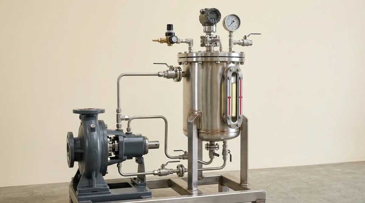
Chemical Pump Mechanical Seal Selection & API 682 Piping Plans: Face Metallurgy, Secondary Elastomers & Flush Systems
A definitive technical engineering standard, mechanical seal selection manual, and API 682 flush plan design protocol for chemical process engineers, plant maintenance managers, and rotating equipment specialists across Ahmedabad, Vatva GIDC, Naroda GIDC, Ankleshwar, Dahej PCPIR, and Gujarat.
Quick Answer
In aggressive chemical manufacturing, dye and pigment synthesis, pharmaceutical bulk drug production, and specialty chemical plants across Gujarat—such as in Vatva GIDC, Naroda GIDC, Ankleshwar, Panoli, and Dahej PCPIR—over 65% of all centrifugal pump failures are initiated by mechanical seal degradation. When transferring corrosive hydrochloric acid, hot sulfuric acid, crystallizing organic dye intermediates, toxic aromatic solvents, or abrasive slurries, selecting the wrong mechanical seal design or an inadequate environmental flushing plan conforming to ISO 5199, ISO 2858, IS 5120, and API 682 standards leads to rapid catastrophic leaks within days. A single engineering mismatch—such as pairing Reaction-Bonded Silicon Carbide (RBSiC) with strong caustic solutions (which leaches free silicon), specifying standard Viton (FKM) elastomers on dynamic amines or ketones (causing rapid swelling and extrusion), or operating a single seal on crystallizing salts without an external flush—destroys seal faces, causes hazardous chemical releases, and forces emergency plant shutdowns. Implementing a structured selection framework—evaluating balance ratios (B = 0.70 - 0.85), face PV limits, FFKM/PTFE secondary seals, and engineered API 682 piping plans (Plan 11, 32, 53B, 54)—guarantees zero-leakage chemical containment and extends mechanical seal life beyond 25,000 continuous operating hours.
Key Takeaways
- Match Seal Face Metallurgy to Fluid Chemistry and Solids Content. Use monolithic direct-sintered SSiC vs SSiC for abrasive slurries; use SSiC vs Resin-Impregnated Carbon for clean lubricating chemicals.
- Select Secondary Elastomers Based on Exact Solvent & Temperature Limits. Deploy Perfluoroelastomers (FFKM / Kalrez) for aggressive aromatic/ketone solvents; use encapsulated PTFE O-rings for universal acid resistance.
- Select the Right API 682 Piping Flush Plan (Single vs Dual Pressurized). Deploy API Plan 11/32 for single seals; deploy API Plan 53B/54 dual pressurized barrier systems for toxic, volatile, or carcinogen fluids.
- Maintain Hydrodynamic Fluid Film Vapor Pressure Margins (ΔP_margin > 1.5 bar). Ensure seal chamber pressure stays sufficiently above fluid bubble point to prevent explosive face vaporization.
Introduction
In the major industrial corridors across Ahmedabad, Vatva GIDC, Naroda GIDC, Ankleshwar, and Dahej PCPIR, chemical manufacturing units transfer thousands of corrosive, toxic, volatile, and abrasive liquid streams daily.
Process engineers and rotating equipment reliability heads face severe sealing demands:
- The Chemical Compatibility Challenge: Process chemicals range from fuming nitric and hydrochloric acids to hot caustics, aromatic solvents, and abrasive slurries. An incorrect seal face or O-ring material dissolves or shatters within hours.
- The Containment Imperative: Toxic chemicals, volatile organic compounds (VOCs), and hazardous air pollutants cannot be allowed to leak into the plant atmosphere, demanding engineered dual barrier sealing systems.
- The Engineering Standard: Implementing a structured seal selection and flush design methodology conforming to ISO 5199, ISO 2858, IS 5120, and API 682 standards—incorporating balance ratio calculations, direct-sintered monolithic silicon carbide faces, FFKM elastomers, and engineered API 682 flush plans—guarantees 100% emission-free operation and extends pump operating life beyond 25,000 hours.
2. Master Chemical Pump Mechanical Seal & API 682 Flush Plan Selection Matrix
Use this technical engineering roadmap when selecting mechanical seals and API piping plans across chemical services:
| Chemical Process Service | Fluid Properties & Severity | Recommended Face Metallurgy | Secondary Elastomer | Recommended API 682 Flush Plan |
|---|---|---|---|---|
| Clean Inorganic Acids (HCl, H_2SO_4) | Highly corrosive, non-lubricating | Monolithic SSiC vs Resin Carbon | Pure Virgin PTFE / FFKM | API Plan 11 (Internal Discharge Flush) |
| Abrasive Dye & Pigment Slurries | High solids (15 - 30%), abrasive | Monolithic SSiC vs Monolithic SSiC | FKM (Viton) / EPDM | API Plan 32 (Clean External Flush) |
| Hot Caustic Soda (> 30% NaOH, 80°C) | Highly alkaline, leaches free silicon | Direct-Sintered SSiC vs Carbon | EPDM (Peroxide-Cured) | API Plan 11 or Plan 21 (With Cooler) |
| Volatile Organic Solvents (DCM, Toluene) | Low boiling point, VOC emission risk | Monolithic SSiC vs Monolithic SSiC | Perfluoroelastomer (FFKM) | API Plan 53B (Pressurized Barrier System) |
| Crystallizing Salts & Organic Intermediates | Precipitates abrasive crystals on cooling | Monolithic SSiC vs Monolithic SSiC | Encapsulated PTFE / FFKM | API Plan 54 (External Barrier) or Plan 62 |
| High-Temperature Thermic Fluids (> 250°C) | Thermal degradation, volatile vapors | Monolithic SSiC vs Diamond-Like Carbon | Inconel Flexible Graphite | API Plan 21 / Plan 54 with Quench |
3. The Hydrodynamic & Thermodynamic Physics of Mechanical Face Sealing
Balance Ratio Kinematics & Face Closing Pressure (P_net = ΔP (B - k) + P_spring)
Mechanical seal balance ratio (B) controls the hydraulic closing force acting on the seal interface:
Interactive Engineering Hydraulic Sizer
Live ISO 5199 / API 610 Dynamic EngineWhere:
- k is fluid pressure gradient factor between the faces (k ≈ 0.50 for linear laminar liquid films).
- P_spring is mechanical spring closing pressure (1.2 - 2.0 bar).
- Balance Ratio Guidelines:
- Unbalanced Seals (B > 1.0, typically 1.15 - 1.25): Used only for low-pressure chemical duties (< 5 bar). High closing forces generate heavy face friction and excessive heat. - Balanced Seals (B < 1.0, typically 0.70 - 0.85): Lowers hydraulic closing pressure, keeping net face pressure low (1.5 - 3.0 bar). This prevents fluid film vaporization and extends seal face life on high-pressure acid pumps up to 35 bar.
Pressure-Velocity (PV) Friction Factor & Thermal Dissipation Limits (PV = P_face · V_sliding)
The frictional heat generation rate at the seal interface is governed by the PV factor:
Where f is the friction coefficient (0.03 - 0.08 for lubricated SSiC vs Carbon; 0.10 - 0.15 for SSiC vs SSiC).
- Maximum PV Ratings:
- Monolithic SSiC vs Resin-Impregnated Carbon: PV_max ≈ 100 bar\cdotm/s. - Monolithic SSiC vs Monolithic SSiC: PV_max ≈ 65 bar\cdotm/s. - Exceeding the material's PV limit causes instantaneous fluid vaporization, face distortion, and rapid thermal cracking.
Fluid Film Vaporization Mechanics & Phase Transition Cavitation at the Interface
- Vapor Pressure Margin (ΔP_margin): The liquid film between seal faces must remain 100% in liquid phase. If local temperature rises or seal chamber pressure drops below the fluid's saturation vapor pressure (P_box < P_vapor + 1.5 bar), flashing occurs. The vapor pockets collapse violently, causing explosive micro-cavitation that pits Silicon Carbide faces and produces high-pitched seal popping.
Chemical Leaching Kinetics of Free Silicon in Caustic Environments (Si + 2NaOH + H_2O \rightarrow Na_2SiO_3 + 2H_2)
- Reaction-Bonded Silicon Carbide (RBSiC) contains 8 - 12% unreacted metallic free silicon. When exposed to hot sodium hydroxide (NaOH > 10% at > 60°C), caustic dissolves the metallic silicon, leaving a porous, spongy carbon matrix that crumbles under load within weeks. Direct-sintered monolithic SSiC contains zero free silicon and is 100% immune to caustic attack.
4. The 4 Critical Mechanical Seal Failure Modes in Gujarat Chemical Plants
Failure Mode 1: Free Silicon Leaching & Pitting in Reaction-Bonded Carbide Faces
- Failure Mechanism: Installing low-cost Reaction-Bonded Silicon Carbide on caustic or nitric acid pumps results in chemical leaching of free silicon binders, pitting face surfaces and creating catastrophic leaks.
- Engineering Solution: Standardize 100% on direct-sintered monolithic alpha Silicon Carbide (SSiC) for all chemical duties.
Failure Mode 2: Secondary Elastomer Chemical Attack, Swelling & Compression Set
- Failure Mechanism: Standard FKM (Viton) O-rings exposed to amines, ketones, or esters swell by > 30%, jamming the dynamic seal sleeve and preventing springs from maintaining face closing force.
- Engineering Solution: Specify genuine Perfluoroelastomer (FFKM / Kalrez) or pure virgin PTFE encapsulated O-rings.
Failure Mode 3: Abrasive Solids Ingress & Crystal Hang-Up Jamming Dynamic Springs
- Failure Mechanism: In slurry or crystallizing services, solids pack inside the rotating multi-spring carrier, freezing the dynamic collar and forcing faces open during thermal expansion.
- Engineering Solution: Install stationary single-spring cartridge seals with springs located entirely outside the process fluid, combined with API Plan 32 or Plan 54 flush systems.
Failure Mode 4: Dry Running & Explosive Phase Vaporization Heat-Checking
- Failure Mechanism: Operating a pump with a closed suction valve or unprimed casing generates intense frictional heat within 30 seconds, causing radial thermal heat-checking cracks across ceramic seal rings.
- Engineering Solution: Install power monitors or dry-run protectors and deploy dual pressurized API Plan 53B barrier fluid systems.
5. Sanitary Materials of Construction & Cleanroom Standards
Direct-Sintered Monolithic Silicon Carbide (SSiC) vs Tungsten Carbide (WC)
- Silicon Carbide Metallurgy: Monolithic alpha SSiC (2800 HV) containing zero free silicon binders, diamond-lapped to ≤ 1 helium light band (0.3 µm) for universal corrosion resistance against all acids, caustics, and abrasives.
- Tungsten Carbide Metallurgy: Nickel-bound Tungsten Carbide (6% Ni-WC, 1600 HV) offering high fracture toughness (12 MPa\cdotm^1/2) for high-shock slurry and boiler feed duties.
High-Purity Antimony & Resin-Impregnated Electro-Graphite Carbon Faces
- Carbon Metallurgy: Fine-grained, self-lubricating electro-graphite impregnated with premium phenolic resin or antimony metal, offering low friction coefficient (f < 0.04) and high PV limits on clean chemical services.
Perfluoroelastomer (FFKM), Fluoroelastomer (FKM) & Pure Virgin PTFE Secondary Seals
- Secondary Elastomers: FFKM (Kalrez / Chemraz) rated up to +315°C with universal chemical resistance, alongside pure virgin PTFE wedge rings and FDA-compliant FKM/EPDM elastomers.
Corrosion-Resistant Hastelloy C-276, Alloy 20 & Duplex SS Wetted Metal Components
- Metallic Hardware: Hastelloy C-276 (UNS N10276) springs, Alloy 20 (UNS N08020) glands, and 2205 Duplex Stainless Steel drive sleeves providing total immunity against chloride stress corrosion cracking and pitting.
6. Step-by-Step Mechanical Seal Selection, Sizing & API Flush Plan SOPs
Execute these structured engineering SOPs when specifying mechanical seals and piping plans:
Phase 1: Chemical Process Duty & Fluid Property Characterization SOP
- Parameter Gathering: Record fluid name, exact concentration (%), operating temperature (°C), suction pressure (P_s), discharge pressure (P_d), vapor pressure (P_v), and solids concentration (% wt).
- Chemical Categorization: Classify fluid into Clean Corrosive, Abrasive Slurry, Crystallizing / Polymerizing, Hot Thermal, or Toxic VOC.
Phase 2: Seal Arrangement & Balance Ratio (B) Calculation SOP
- Arrangement Selection: Single Cartridge (clean/non-toxic) vs Dual Unpressurized Plan 52 (low hazard) vs Dual Pressurized Plan 53B/54 (toxic/flammable/slurry).
- Balance Sizing: Verify balanced hydraulic design (B = 0.72 - 0.78) for all process pressures exceeding 3.0 bar.
Phase 3: Seal Face Metallurgy & Secondary Elastomer Matching SOP
- Face Pairing: Select direct-sintered SSiC vs SSiC for slurries and caustics; select SSiC vs Carbon for clean acids and solvents.
- Elastomer Verification: Cross-reference fluid against chemical compatibility charts; specify FFKM for aromatic solvents and strong acids.
Phase 4: API 682 Piping Flush Plan Design & Sizing SOP
- Flush Plan Selection: Size API Plan 11 orifice for Q_flush ≥ 4.0 - 8.0 L/min to remove frictional heat. For abrasive slurries, install API Plan 32 clean external flush (1.0 - 2.0 bar above seal chamber pressure).
- Barrier Fluid System: For API Plan 53B, size bladder accumulator and charge barrier fluid (synthetic PAO or water/glycol) to 1.5 - 2.0 bar above maximum seal chamber pressure.
Phase 5: Cartridge Assembly, Bench Pressure Leak Testing & Runout SOP
- Cartridge Assembly: Assemble seal components into a pre-set cartridge with setting clips.
- Bench Hydrotest: Pressurize cartridge with air/water to 3.0 bar for 5 minutes on the test bench; confirm zero pressure drop and zero face weeping.
Phase 6: On-Site Installation, Dual Laser Realignment & Commissioning SOP
- Alignment & Commissioning: Install cartridge on pump shaft; tighten gland nuts evenly in criss-cross pattern; remove setting clips; perform dual laser alignment (≤ 0.03 mm); vent seal chamber completely before energizing motor.
7. Worked Gujarat Chemical & Pharmaceutical Industrial Case Studies
Case 1: Vatva GIDC Reactive Dye Slurry Pump Plan 32 External Flush Retrofit
- Plant Context: A synthetic organic dye plant in Vatva GIDC pumping abrasive reactive blue dye intermediate slurry (22% solids, 65°C).
- Problem: Single mechanical seals failed every 10 to 14 days due to dye crystals embedding in carbon faces and packing dynamic springs.
- Action Plan: Replaced single seal with a heavy-duty cartridge seal featuring direct-sintered SSiC vs SSiC faces, isolated external springs, and an API Plan 32 clean condensate flush (1.5 bar above box pressure).
- Outcome: Seal operating life extended from 2 weeks to over 16 consecutive operating months; saved Rs 6,40,000 in avoided overhauls and lost batch production.
Case 2: Ankleshwar GIDC Bulk Drug API Methylene Chloride Pump Plan 53B Upgrade
- Plant Context: A bulk pharmaceutical API synthesis plant in Ankleshwar GIDC pumping volatile methylene chloride (DCM) solvent (25°C, vapor pressure 0.58 bar).
- Problem: Single mechanical seals suffered explosive face vaporization, leaking toxic DCM fumes and failing factory environmental audits.
- Action Plan: Retrofitted pumps with API 682 Plan 53B dual pressurized cartridge seals with synthetic PAO barrier fluid pressurized to 4.5 bar (2.0 bar above box pressure).
- Outcome: Zero solvent vapor emissions; continuous leak-free operation over 24 consecutive operating months; achieved 100% environmental compliance.
Case 3: Dahej PCPIR Petrochemical Caustic Scrubber Pump SSiC Face Conversion
- Plant Context: A petrochemical plant in Dahej PCPIR circulating 32% NaOH caustic solution at 75°C through wet gas scrubbers.
- Problem: Mechanical seals failed every 6 weeks due to severe face pitting and roughness.
- Action Plan: Metallurgical RCFA revealed Reaction-Bonded Silicon Carbide (RBSiC) was failing via free silicon leaching; converted to monolithic direct-sintered SSiC with peroxide-cured EPDM elastomers.
- Outcome: Face pitting eliminated 100%; seal operating life extended beyond 28 consecutive operating months.
Case 4: Naroda GIDC Concentrated Nitric Acid Pump FFKM Elastomer Upgrade
- Plant Context: A specialty chemical plant in Naroda GIDC transferring 68% HNO_3 concentrated nitric acid at 45°C.
- Problem: Standard Viton O-rings turned brittle and charred within 3 weeks, blowing out seal secondary containment.
- Action Plan: Replaced all secondary seals with genuine Perfluoroelastomer (FFKM / Kalrez) O-rings and direct-sintered SSiC seal faces.
- Outcome: 100% acid containment across 30 consecutive operating months with zero elastomer degradation.
Case 5: Surat Textile Processing House Hot Dye Liquid Seal Plan 11 Orifice Tuning
- Plant Context: A textile processing mill in Surat operating twenty high-temperature dyeing circulation pumps (130°C pressurized liquor).
- Problem: Mechanical seal faces overheated and cracked due to inadequate cooling flush flow through undersized 1.5 mm orifices.
- Action Plan: Enlarged API Plan 11 flush orifice to 3.5 mm, increasing circulation flow to 6.5 L/min; upgraded faces to SSiC vs SSiC.
- Outcome: Seal chamber operating temperature dropped by 38°C; seal life extended from 3 months to 22 months.
Case 6: Panoli GIDC Agrochemical Synthesis Hot Solvent Cartridge Seal Upgrade
- Plant Context: A pesticide synthesis unit in Panoli GIDC pumping hot chlorobenzene solvent (115°C).
- Problem: Component mechanical seals were improperly installed by plant technicians, leading to shaft scoring and recurring leaks.
- Action Plan: Converted pump frames to pre-set cartridge mechanical seals with FFKM secondary seals and API Plan 52 unpressurized buffer systems.
- Outcome: Installation errors eliminated; pump running continuously for over 20 consecutive operating months.
8. Step-by-Step Chemical Mechanical Seal Selection Flowchart
Follow this structured engineering guide when selecting seal types and flush piping:
| Fluid Chemistry & Solids Category | Primary Mechanical Seal Design | Seal Face Metallurgy | Secondary Elastomer | Mandatory API 682 Flush Plan |
|---|---|---|---|---|
| Clean Corrosive Acid (HCl, HNO_3) | Single Balanced Cartridge | Monolithic SSiC vs Carbon | FFKM / Pure Virgin PTFE | API Plan 11 |
| Abrasive Slurry (> 5% Solids) | Single Cartridge (External Spring) | Monolithic SSiC vs SSiC | FKM / EPDM | API Plan 32 (Clean Flush) |
| Strong Caustic Solution (NaOH) | Single Balanced Cartridge | Direct-Sintered SSiC vs Carbon | Peroxide-Cured EPDM | API Plan 11 / Plan 21 |
| Toxic / Flammable VOC Solvent | Dual Pressurized Cartridge | Monolithic SSiC vs SSiC | Perfluoroelastomer (FFKM) | API Plan 53B / Plan 54 |
| Crystallizing Organic Salt | Dual Pressurized Cartridge | Monolithic SSiC vs SSiC | Encapsulated PTFE / FFKM | API Plan 54 (External Flush) |
| Hot Thermal Fluid (> 200°C) | High-Temp Single / Dual | Monolithic SSiC vs DLC | Flexible Graphite | API Plan 21 / Plan 54 |
9. Comprehensive Master Chemical Pump Mechanical Seal (FAT) Checklist
Execute this quality verification protocol during mechanical seal selection and installation:
Chemical Process Pump Mechanical Seal Selection & Installation Protocol
10. Summary & Mechanical Seal Selection and Overhaul Services in Gujarat
Eliminating hazardous chemical leaks, matching seal face metallurgies to process fluid chemistry conforming to ISO 5199 and API 682 standards, designing engineered API piping flush plans, and extending chemical pump seal life beyond 25,000 hours across Ahmedabad, Vatva GIDC, Naroda GIDC, Ankleshwar, and Dahej PCPIR—by utilizing direct-sintered monolithic Silicon Carbide, genuine FFKM elastomers, and dynamic balancing to Grade G2.5—is the proven engineering standard for modern chemical plant reliability.
Teflow Pumps operates a specialized rotating machinery overhaul facility in Ahmedabad, providing engineered mechanical seal selection audits, API 682 flush plan design, cartridge seal reconditioning, diamond lapping, dynamic balancing, and genuine chemical spares across Gujarat conforming to ISO 5199, ISO 2858, IS 5120, and API 682 standards.
- Direct Technical & Emergency Helpline: +91 98251 62709
- WhatsApp Technical Desk: Share your chemical process fluid, operating temperature (°C), pump model, or current seal failure symptoms to wa.me/919825162709 for immediate engineering diagnostics, seal selection advice, and formal quotation.
- Request an On-Site Mechanical Seal Audit: Contact our senior rotating equipment reliability engineers for plant seal surveys, API flush plan retrofits, and formal AMC service quotes.