
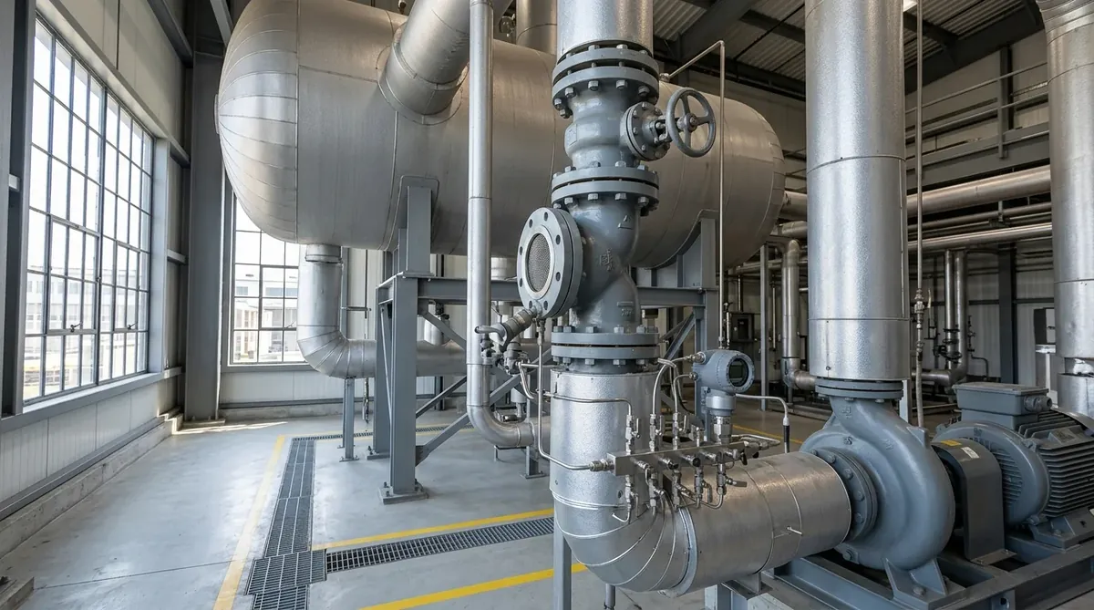
Boiler Feed Water Pump Cavitation & NPSH Fixes: High-Temperature Thermodynamics & Overhaul Manual
A definitive high-pressure steam boiler hydraulics standard, deaerator transient thermodynamic flashing mathematical derivation manual, and multi-stage boiler feed water pump overhaul guide for maintenance engineers, boiler house in-charges, and utility superintendents across Narol, Odhav, Vatva GIDC, Surat, and Gujarat.
Quick Answer
In the high-pressure steam generation facilities, textile processing dyehouses, chemical synthesis plants, and captive power utilities of Gujarat—spanning Ahmedabad (Narol, Odhav, Vatva GIDC), Surat, Ankleshwar, and Dahej—boiler feed water pump (BFP) cavitation is the leading root cause of catastrophic multi-stage rotor seizure, stage diffuser cracking, and mechanical seal destruction. Because boiler feed water operates near saturated boiling conditions inside the deaerator (105°C - 165°C), the liquid's vapor pressure (P_vap) equals the vessel pressure (P_deaerator), rendering pressure head useless for suction energy (h_pressure - h_vapor = 0). Consequently, available Net Positive Suction Head (NPSHa) is generated almost entirely by static elevation head (Z_deaerator): NPSHa (meters) = Z_static (m) - h_friction (m). During sudden boiler steam load drops or turbine trips (load rejection), deaerator pressure decays faster than feedwater cools in the suction downcomer pipe, triggering severe thermodynamic flashing. Maintaining NPSHa ≥ NPSHr + 1.8 meters (NPSH Margin Ratio ≥ 1.50) conforming to ISO 5199, API 610, and Hydraulic Institute (HI 9.6.1) standards eliminates thermal cavitation.
Key Takeaways
- Master Saturated Feedwater NPSHa Physics. Realize that at saturated deaerator boiling conditions, available suction head depends solely on static height: NPSHa ≈ Z_static - h_friction.
- Model Transient Deaerator Load Rejection Flashing. Size deaerator storage tank height to provide buffer head during rapid boiler steam pressure decays.
- Inspect Multi-Stage Balance Drum Clearance. Maintain balance drum radial clearances within 0.15 - 0.22 mm to prevent hot internal bypass recirculation.
- Utilize API Plan 23 Mechanical Seal Cooling. Install closed-loop pumping ring heat exchangers to maintain seal face temperatures below 80°C.
Introduction
Across Gujarat's continuous industrial steam utilities—including the high-volume coal and gas-fired boiler houses of Narol and Surat textile mills, the chemical process steam generation plants of Vatva GIDC and Odhav, the pharmaceutical co-generation units of Ankleshwar, and the massive petrochemical steam crackers of Dahej—boiler feed water pumps operate under the most severe thermodynamic conditions in industrial machinery.
Boiler feed water pumps must inject deaerated water at temperatures ranging from 105°C to 165°C into boiler steam drums against pressures exceeding 20 to 120 bar:
- The High-Temperature Dilemma: Inside a thermal deaerator, feed water is maintained at its saturated boiling point to strip dissolved oxygen. This means absolute vessel pressure is identical to the liquid's vapor pressure (P_deaerator = P_vapor).
- The Physical Consequence: Saturated boiling leaves zero positive pressure margin at the liquid surface. The pump must rely completely on the static height of the deaerator tank above the pump centerline (Z_deaerator) to satisfy the pump's required Net Positive Suction Head (NPSHr).
- The Transient Trap: During sudden steam demand changes or boiler trips, deaerator pressure drops rapidly. Hot water residing inside the long suction downcomer pipe flashes violently into steam bubbles, starving the pump, causing severe cavitation hammering, and triggering catastrophic rotor seizure within seconds.
- The Engineering Standard: Following ISO 5199, API 610, and Hydraulic Institute (HI 9.6.1) standards—maintaining adequate deaerator elevation, sizing low-velocity suction downcomers, inspecting multi-stage balance drum clearances, and installing API Plan 23 seal coolers—ensures 100% boiler uptime and prevents costly boiler trips.
2. Master High-Temperature Feedwater Cavitation Comparison Matrix
Review the governing thermodynamic parameters, physical mechanisms, and engineering thresholds for boiler feed water pump suction systems:
| Hydraulic Parameter | Physical Definition | Mathematical Formulation | Safe Operating Standard | Risk If Violated |
|---|---|---|---|---|
| Saturated NPSHa | Net Head Available from Static Elevation | NPSHa = Z_static - h_friction | NPSHa ≥ NPSHr + 1.8 m | Suction flashing & cavitation |
| Deaerator Static Head (Z) | Elevation Difference: Tank to Pump | Z = Elevation_deaerator - Elevation_pump | Z_static ≥ 4.5 - 7.5 meters | Inadequate static driving head |
| Downcomer Velocity (v_s) | Fluid Velocity in Suction Downcomer | v_s = [Q_m³/h] / [2827.43 · D_inner²] | v_s ≤ 0.8 - 1.2 m/s | High friction drop & turbulence |
| Balance Drum Leakage | Internal High-Pressure Bypass Flow | Q_leak \propto [ΔP · c_radial³] / [µ· L] | c_radial ≤ 0.18 - 0.22 mm | Internal thermal vaporization |
| Minimum Flow Bypass | Thermal Protection Flow at Shutoff | Q_min = [3600 · P_shaft] / [ρ· c_p · ΔT_allow] | Q_min ≥ 20% - 30% · Q_BEP | Explosive steam binding in casing |
3. The Fluid Dynamics Physics & High-Temperature NPSHa Derivations
Saturated Feedwater Net Positive Suction Head Equation (NPSHa ≈ Z_static - h_f)
The universal formula for Net Positive Suction Head Available (NPSHa) is:
Interactive Boiler Feed Water Pump Sizing Calculator
Live ISO 5199 / API 610 Dynamic EngineBecause boiler feedwater inside a thermal deaerator resides at saturated thermodynamic equilibrium:
Therefore, the pressure term reduces to zero:
The actual available suction head reduces strictly to:
- Engineering Reality: In boiler feedwater applications, atmospheric or vessel pressure provides zero suction assist. Every millimeter of available head must come from the physical height of the deaerator tank (Z_static).
Deaerator Transient Pressure Decay Rate Math ((dP_d) / (dt))
When boiler steam demand drops abruptly (e.g., turbine trip or stenter halt), incoming cold condensate continues entering the deaerator while heating steam decreases, causing deaerator pressure to decay rapidly:
Where M_water is the water mass in storage, W_condensate is incoming condensate flow, and h is enthalpy.
- If the suction downcomer residence time (t_residence = (L_pipe) / (v_downcomer)) is long, water entering the pump suction is hotter than the new, lower deaerator pressure allows (P_actual < P_vap(T_water)), causing instantaneous suction downcomer flashing.
Thermodynamic Vapor Flashing & Latent Heat Cavitation Volume Physics
Unlike cold water cavitation—where vapor bubbles collapse with loud mechanical snapping—high-temperature water cavitation involves massive thermodynamic vapor generation. At 130°C, 1 liter of water flashes into 310 liters of steam vapor, completely choking multi-stage impeller eyes (steam binding) and causing immediate dry running of interstage bushings.
Balance Drum Leakage & Axial Thrust Balancing Flow Recirculation Math
In multi-stage ring-section boiler feed pumps, all impellers face in the same direction, generating massive axial thrust (10 - 50 kN). A cylindrical balance drum or balancing disc offsets this thrust by channeling discharge liquid through a narrow annular throttling clearance (c_radial = 0.15 - 0.22 mm):
- Overheating Hazard: When the balance drum abrades (c_radial > 0.45 mm), leakage increases from 3 m³/h to > 14 m³/h. This hot leakage returns directly to the suction chamber, raising suction temperature by 5°C - 12°C, inducing immediate thermal cavitation.
Minimum Flow Bypass Sizing Equation (Q_min = [3600 · P_shaft] / [ρ· c_p · ΔT_allow])
To prevent water from flashing into steam inside multi-stage casings during low boiler demand:
- Automatic Recirculation Valve (ARC Valve): An automatic ARC valve must be installed on the pump discharge to open a minimum flow bypass line back to the deaerator whenever boiler flow drops below 25% · Q_BEP.
API Plan 23 Mechanical Seal Pumping Ring Heat Balance Math
Mechanical seals on boiler feed pumps operate using API Plan 23:
An internal shaft-mounted pumping ring continuously circulates seal chamber water through an external air-cooled or shell-and-tube heat exchanger, cooling the fluid from 140°C to < 65°C to prevent seal face vapor flashing.
4. The 6 Critical Causes of Boiler Feed Water Pump Cavitation
Cause 1: Deaerator Sudden Pressure Decay & Cold Water Quenching Flashing
- Mechanism: Sudden boiler load reduction causes deaerator steam pressure to collapse while hot water remains in the suction line.
- Impact: Feedwater flashes into steam inside the suction downcomer pipe; pump suffers severe steam binding and vibration.
- Fix: Install an anti-flash deaerator control loop or increase suction downcomer pipe diameter to minimize friction.
Cause 2: Suction Downcomer Strainer Silt & Rust Magnetite Clogging
- Mechanism: Rust flakes, boiler scale, and magnetite particles accumulate on the fine mesh of the suction strainer.
- Impact: Strainer pressure drop increases by 0.4 - 0.8 bar (4 - 8 meters head loss), destroying available NPSHa.
- Fix: Install low-loss basket strainers with differential pressure transmitters; clean during periodic outages.
Cause 3: Undersized Suction Piping & High Flow Velocity Friction Drops
- Mechanism: Designing suction downcomer piping with fluid velocity v > 1.8 m/s.
- Impact: High friction head loss consumes precious static elevation head (h_f > 1.5 m).
- Fix: Upsize suction downcomer piping to ensure velocity v_suction ≤ 0.8 - 1.0 m/s.
Cause 4: Worn Multi-Stage Balance Drum Bushing Recirculation Overheating
- Mechanism: High-pressure balance drum annular clearance expands beyond OEM limits due to erosion.
- Impact: Hot discharge liquid dumps back into pump suction, raising inlet temperature and triggering thermal cavitation.
- Fix: Disassemble multi-stage casing and machine new Stellite-hardfaced balance drum to OEM clearance (0.18 mm).
Cause 5: Off-BEP Low-Flow Thermal Vaporization & Minimum Flow Line Failure
- Mechanism: Boiler operating at low steaming rate with jammed or undersized ARC minimum flow bypass line.
- Impact: Hydraulic power converts into heat, boiling the water inside closed pump stages within 45 seconds.
- Fix: Overhaul ARC minimum flow valve; verify bypass flow rate meets minimum thermal dissipation requirements.
Cause 6: Impeller First-Stage Suction Eye Cavitation Erosion & Thinning
- Mechanism: Long-term exposure to marginal NPSH conditions creates microscopic cavitation pitting on first-stage vanes.
- Impact: Vane leading edges thin and break off, increasing required NPSHr and causing progressive performance collapse.
- Fix: Install a replacement high-suction-specific-speed (N_ss) first-stage impeller cast from CA6NM chrome steel.
5. Step-by-Step Multi-Stage BFP Teardown, Metrology & Overhaul SOPs
Execute this structured engineering protocol when diagnosing, overhauling, or re-commissioning boiler feed water pumps:
Phase 1: Field Thermodynamic Temperature (T_s) & Static Head (Z) Audit SOP
- Deaerator Survey: Measure physical height (Z_static) from deaerator minimum water level to pump suction centerline.
- Operating Point Audit: Log deaerator operating pressure (P_d) and water temperature (T_s); compute available static NPSHa = Z_static - h_friction.
Phase 2: Suction Downcomer Line Velocity (v ≤ 1.0 m/s) Audit SOP
- Velocity Calculation: Compute downcomer velocity v = [Q_m³/h] / [2827.43 · D_inner²].
- Friction Verification: Verify total friction head loss in suction line is ≤ 0.30 meters.
Phase 3: Multi-Stage Casing Teardown & Stage Diffuser Metrology SOP
- Teardown: Unbolt casing tie-rods; extract multi-stage impellers, diffusers, and stage casing rings in workshop.
- Metrology Inspection:
- Measure first-stage impeller eye diameter (D_eye) and vane leading edge thickness. - Measure stage diffuser return channel passages for cavitation pitting and erosion wear.
Phase 4: Balance Drum & Interstage Bushing Precision Machining SOP
- Lathe Machining: Machine new balance drum and stationary balance bushing from Stellite-hardfaced chrome steel.
- Clearance Setting: Set radial clearance to 0.15 - 0.20 mm; machine interstage bushings to 0.20 - 0.25 mm.
Phase 5: Dynamic Rotor Balancing to ISO 5199 Grade G2.5 SOP
- Dynamic Balancing: Assemble multi-stage rotor stack on balancing machine mandrel.
- Balance Certification: Dynamically balance the complete assembled rotor to < 1.0 g\cdotmm/kg conforming to ISO 5199 Grade G2.5.
Phase 6: Laser Alignment, API Plan 23 Venting & Warm-Up Commissioning SOP
- Laser Alignment: Perform cold and hot thermal growth laser alignment (≤ 0.03 mm offset).
- Warm-Up Protocol: Open casing warm-up bypass line; ensure uniform casing heating (< 10°C top-to-bottom differential) before startup to prevent thermal bow rotor rub.
6. Materials of Construction, Metallurgy & High-Temperature Standards
Chrome Steel (CA6NM / 13Cr4Ni) Impellers & Diffusers
- Cavitation & Thermal Shock Resistance: Investment-cast CA6NM (13% Cr, 4% Ni) martensitic stainless steel provides extreme tensile strength (> 750 MPa), superior cavitation pitting resistance, and thermal fatigue endurance in boiler feedwater up to 180°C.
Martensitic Stainless Steel (SS410 / SS420) Shafts & Sleeves
- Torsional Rigidity: Quenched and tempered SS410/SS420 shafts with precision-ground bearing journals maintain high torsional stiffness and zero shaft deflection under multi-stage hydraulic loads.
Stellite Hardfaced Balance Drums & Bushings
- Anti-Galling Performance: Plasma-transferred arc (PTA) Stellite Grade 6 weld overlay on balance drums provides high hardness (> 42 HRC) and complete galling resistance during momentary dry running or startup transients.
Monolithic Direct-Sintered Silicon Carbide (SSiC) Seal Faces
- Thermal Conductivity: Direct-sintered SSiC vs SSiC mechanical seal faces provide high thermal conductivity (120 W/m\cdotK) and zero thermal distortion under API Plan 23 cooling loops.
7. The Boiler Engineer's BFP Cavitation Troubleshooting Decision Matrix
Follow this structured engineering guide when troubleshooting boiler feed water pump cavitation and acoustic noise:
| Observed Symptom | Underlying Root Cause | Operating Metric Violation | Corrective Engineering Action |
|---|---|---|---|
| Loud Gravel Noise During Load Drop | Deaerator Transient Pressure Decay | NPSHa < NPSHr during transient | Install anti-flash bypass or elevate deaerator |
| High Vibration (> 7.5 mm/s) at Full Load | Suction Strainer Magnetite Clogging | Strainer ΔP > 0.40 bar | Clean suction strainer basket; inspect mesh |
| Hot Suction Housing (> 125°C) | Worn Balance Drum Clearance | c_radial > 0.40 mm (High leakage) | Overhaul balance drum; machine new bushing |
| Mechanical Seal Steaming & Leaking | API Plan 23 Cooler Clogging / Air Trap | Seal chamber temperature > 90°C | Flush Plan 23 cooler; vent air from seal gland |
| Stage Casing Squeal at Low Steaming | ARC Minimum Flow Bypass Blocked | Flow < 20% BEP without bypass | Overhaul ARC valve; clear minimum flow orifice |
8. Worked Gujarat Textile Mill, Chemical Steam & Power Plant Case Studies
Case 1: Narol Continuous Textile Stenter Boiler Feed Pump Cavitation Fix
- Plant Context: A continuous textile processing mill in Narol operating three high-pressure steam boilers (18 bar, 135°C) fed by a 6-stage ring-section boiler feed pump (45 m³/h, 240 m head).
- Problem: The boiler feed pump suffered violent cavitation knocking whenever the main stenter steam valves closed abruptly. Mechanical seals failed every 4 to 6 weeks, costing over 4.5 lakh INR in downtime.
- Root Cause:
- Deaerator storage tank height was only 3.2 meters above pump centerline (Z_static = 3.2 m). - Suction downcomer line friction loss was 0.85 m, leaving net available head of only NPSHa = 2.35 m, whereas pump NPSHr = 2.80 m (NPSHa Deficit = -0.45 m during load changes).
- Action Plan: Teflow Pumps engineering team:
- Overhauled multi-stage pump in our Ahmedabad workshop; replaced eroded bronze impellers with precision CA6NM chrome steel impellers. - Installed a high-suction-specific-speed (N_ss) first-stage impeller, reducing required NPSHr from 2.80 m to 1.65 m. - Re-machined balance drum to 0.18 mm clearance and dynamically balanced rotor to ISO 5199 Grade G2.5. - Re-routed suction piping with a 125 mm line to reduce downcomer friction from 0.85 m to 0.18 m.
- Outcome: Restored positive NPSH margin of +1.37 meters; completely eliminated cavitation noise; boiler feed pumps operating continuously for over 26 months without seal failure.
Case 2: Vatva GIDC Chemical Plant Steam Boiler Feed Pump NPSH Upgrade
- Plant Context: A specialty organic intermediate plant in Vatva GIDC operating a 10 TPH boiler with feedwater at 110°C.
- Problem: Rust and magnetite flakes clogged the suction Y-strainer, causing suction starvation and stage bushing seizure.
- Action Plan: Replaced Y-strainer with a low-loss duplex magnetic basket strainer with a differential pressure switch.
- Outcome: Maintained suction head loss below 0.15 m; zero bushing seizures.
Case 3: Odhav Industrial Steam Boiler Multi-Stage Pump Overhaul
- Plant Context: An industrial manufacturing boiler in Odhav suffering high vibration (9.2 mm/s RMS) and loss of discharge pressure.
- Problem: Balance drum clearance had worn to 0.62 mm, dumping 8.5 m³/h of hot water into pump suction.
- Action Plan: Fitted Stellite-hardfaced balance drum and dynamically balanced rotor stack to ISO 5199 Grade G2.5.
- Outcome: Discharge pressure restored to 28 bar; vibration dropped to 1.15 mm/s RMS (Zone A).
Case 4: Surat Synthetic Yarn Spinning Plant Boiler Feed Flashing Remediation
- Plant Context: A synthetic yarn spinning facility in Surat operating high-pressure boiler feed pumps (55 bar).
- Problem: Rapid boiler steam fluctuations caused frequent feedwater flashing in the suction downcomer pipe.
- Action Plan: Installed a dedicated anti-flash steam injection loop into the suction downcomer and upsized suction line.
- Outcome: Eliminated thermal flashing; continuous boiler uptime achieved.
Case 5: Ankleshwar GIDC Pharma Co-Gen Boiler Feed Pump Overhaul
- Plant Context: A pharmaceutical co-generation power plant in Ankleshwar GIDC operating an 8-stage boiler feed pump.
- Problem: Mechanical seal faces suffered thermal cracking due to air binding in the API Plan 23 seal cooler.
- Action Plan: Re-piped API Plan 23 cooler with continuous high-point vent line and installed SSiC seal faces.
- Outcome: Seal face operating temperature stabilized at 58°C; extended seal lifespan beyond 36 months.
Case 6: Dahej PCPIR Petrochemical High-Pressure Feedwater Pump Upgrade
- Plant Context: A petrochemical captive power plant in Dahej PCPIR operating high-flow multi-stage boiler feed pumps (160 m³/h, 85 bar).
- Problem: Impeller first-stage cavitation erosion caused high axial rotor vibration.
- Action Plan: Upgraded first-stage impeller to Super Duplex SS 2507 and retrofitted axial flow inducer.
- Outcome: Reduced required NPSHr by 45%; vibration dropped to < 1.10 mm/s RMS.
9. Comprehensive Master Boiler Feed Water Pump Overhaul Checklist
Execute this metrology, clearance verification, and commissioning protocol during boiler feed pump overhauls:
Boiler Feed Water Pump Overhaul & Cavitation Elimination Protocol
10. Summary & Specialized Boiler Feed Pump Overhaul Services in Gujarat & India
Eliminating boiler feed water pump cavitation—mastering saturated feedwater static head physics, preventing deaerator transient flashing, optimizing low-velocity suction downcomers, precision machining Stellite-hardfaced balance drums to 0.18 mm clearance, and dynamically balancing multi-stage rotor stacks to ISO 5199 Grade G2.5 across Narol, Odhav, Vatva GIDC, Surat, Ankleshwar, and Dahej—conforming to ISO 5199, API 610, and DIN 24255 standards—is the proven engineering standard for industrial boiler reliability and plant safety.
Partnering directly with an established Gujarat rotating machinery manufacturer provides boiler house in-charges, utility superintendents, and plant maintenance engineers with immediate technical access to on-site boiler feedwater diagnostic teams, ultrasonic flow meters, precision inside micrometer metrology workshops, multi-stage dynamic balancing machines, and genuine spares dispatched directly from our Ahmedabad factory. Our technical engineers provide emergency on-site troubleshooting, turnkey multi-stage overhauls, and complete deaerator suction piping re-engineering.
Teflow Pumps operates a specialized industrial machinery manufacturing and service facility in Ahmedabad, providing emergency multi-stage boiler feed water pump overhauls, CA6NM chrome steel impeller casting, Stellite hardfacing, balance drum machining, dynamic balancing, laser alignment, and genuine rotating equipment spares across Gujarat and India conforming to ISO 5199, API 610, DIN 24255, and IS 5120 standards.
- Direct Technical & Emergency Helpline: +91 98251 62709
- WhatsApp Technical Desk: Share deaerator height drawings (Z_static), operating water temperatures (°C), boiler steam pressures (bar), pump nameplate photos, or cavitation knocking audio to wa.me/919825162709 for immediate technical review, NPSHa calculation, and formal quotation.
- Request an On-Site Boiler Feed Pump Audit & Overhaul Proposal: Contact our senior rotating equipment engineers for emergency plant surveys, multi-stage overhaul proposals, and formal quotation. Our engineering team conducts comprehensive thermal evaluations, verifies ISO 5199 criteria, provides precision on-site or workshop reconditioning, and dynamically balances overhauled hot oil pumps to ensure maximum uptime across Gujarat's textile and chemical processing mills. We provide rapid technical evaluations, on-site plant surveys, and formal quotes.