
Actual Pump Flow Rate Formula: Sizing Math, Internal Slip Physics & Wear Ring Clearance Overhaul Manual
A definitive hydraulic flow degradation standard, internal annular slip mathematical derivation manual, and centrifugal pump volumetric efficiency restoration guide for plant maintenance engineers, reliability leads, and rotating equipment specialists across Vatva GIDC, Narol, Odhav, Surat, and Gujarat.
Quick Answer
In the chemical manufacturing complexes, pharmaceutical bulk drug facilities, textile processing mills, and heavy industrial plants of Gujarat—spanning Ahmedabad (Vatva GIDC, Narol, Odhav), Surat, Ankleshwar, and Dahej—understanding the difference between theoretical pump capacity and actual delivered flow rate is essential for process control. While catalog pump curves depict ideal flow rates under laboratory test conditions with new machinery, operating pumps suffer from internal hydraulic slip and volumetric leakage. The actual delivered volumetric flow rate (Q_actual) is calculated by subtracting internal slip leakage (Q_slip) from theoretical geometric capacity: Q_actual = Q_theoretical - Q_slip = Q_theoretical · \eta_vol. In centrifugal process pumps, internal slip is driven by pressurized fluid leaking through the annular clearance gap between the rotating impeller neck and stationary casing wear ring: Q_slip (m³/h) = 3600 · C_d · (π· D_ring · c_radial) · √(2g · ΔH_stage). When radial wear ring clearance (c_radial) doubles from 0.25 mm to 0.60 mm due to abrasive chemical slurry or cavitation erosion, internal slip increases by 140%, causing delivered flow to drop by 15%-25% conforming to ISO 5199, ISO 2858, and DIN 24255 standards.
Key Takeaways
- Master the Actual Flow Rate Equation. Calculate delivered pump capacity using Q_actual = Q_theoretical - Q_slip = Q_theoretical · \eta_vol.
- Model Annular Wear Ring Leakage. Calculate internal slip past wear rings using Q_slip = C_d · A_annulus · √(2g ΔH).
- Identify Volumetric Efficiency Decay. Monitor \eta_vol; when volumetric efficiency falls below 88%, schedule workshop refurbishment.
- Restore OEM Metrology Clearances. Machine replacement wear rings to maintain radial clearances within 0.20 - 0.28 mm to eliminate slip.
Introduction
Across Gujarat's continuous process manufacturing plants—including the large chemical synthesis corridors of Vatva GIDC and Odhav, the pharmaceutical bulk drug facilities of Ankleshwar, the high-volume textile mills of Narol and Surat, and the petrochemical units of Dahej—pumping systems are sized to deliver exact process flow rates.
However, after months of continuous chemical operation, process operators notice that reaction vessels take longer to fill, distillation columns experience reduced reflux, and discharge pressure gauges read lower than rated values:
- The Discrepancy: The pump motor is running at full synchronous speed and drawing normal electrical power, but delivered liquid volume at the discharge flow meter is 15%-30% below catalog test values.
- The Root Cause: This shortfall is caused by internal hydraulic slip—liquid escaping from the high-pressure volute chamber backward into the low-pressure suction eye through expanded internal clearances.
- The Compounding Energy Waste: Internal slip forces the pump to continuously re-pressurize and re-accelerate recirculating fluid, wasting electrical power and generating frictional heat inside the casing.
- The Engineering Standard: Following ISO 5199, ISO 2858, and DIN 24255 standards—mastering actual flow rate equations, performing field ultrasonic flow audits, measuring wear ring clearances with micrometers, and restoring precision tolerances—ensures optimal process yield and plant energy efficiency.
2. Master Theoretical vs Actual Flow Rate Comparison Matrix
Review the governing mathematical formulas, physical definitions, and practical plant examples for theoretical versus actual pump flow rates:
| Flow Parameter | Engineering Metric | Governing Metric Formula | Practical Plant Example (Q_rated = 100 m³/h, H = 40 m) | Physical Mechanism |
|---|---|---|---|---|
| Theoretical Flow (Q_theo) | Ideal Test Curve Capacity | Q_theo = Flow at duty head on factory curve | Q_theo = 100.0 m³/h | Hydraulic design capacity with 0.20 mm new clearances |
| Internal Slip (Q_slip) | Annular Recirculation Loss | Q_slip = 3600 C_d A_gap √(2g ΔH) | Q_slip = 18.4 m³/h (Worn ring: 0.65 mm) | Pressurized fluid leaking back to suction eye |
| Actual Flow (Q_actual) | Net Delivered Capacity | Q_actual = Q_theo - Q_slip | Q_actual = 100.0 - 18.4 = 81.6 m³/h | Real fluid volume delivered into process piping |
| Volumetric Efficiency (\eta_vol) | Flow Retention Ratio | \eta_vol = (Q_actual) / (Q_theo) × 100 | \eta_vol = (81.6) / (100.0) × 100 = 81.6% | Percentage of energized fluid reaching process |
3. The Fluid Dynamics Physics & Internal Slip Mathematical Derivations
Centrifugal Pump Actual Flow Formula (Q_actual = Q_rated - Q_slip)
The actual volumetric flow rate delivered by a centrifugal pump (Q_actual) is defined as the theoretical impeller discharge capacity minus internal parasitic slip losses:
Interactive Engineering Hydraulic Sizer
Live ISO 5199 / API 610 Dynamic EngineWhere:
- Q_theoretical is the theoretical capacity of the impeller at the operating dynamic head (H).
- Q_slip is the sum of annular wear ring bypass flow (Q_wear ring), casing cutwater recirculation (Q_cutwater), and seal balance flush recirculation (Q_flush).
- \eta_vol is the volumetric efficiency (0.94 - 0.98 for new pumps; < 0.82 for worn pumps).
Annular Wear Ring Orifice Flow Derivation (Q_slip = C_d A √(2g ΔH))
In a closed-impeller centrifugal pump, the pressure difference between the high-pressure impeller discharge chamber (P_d) and low-pressure suction eye (P_s) drives fluid across the annular wear ring clearance gap.
The cross-sectional annular area of the gap (A_annulus) is:
Where:
- D_ring is the mean wear ring diameter in meters.
- c_radial is the radial clearance gap in meters (c_radial = (D_casing bore - D_impeller hub) / (2)).
Applying the orifice flow equation across differential pressure head (ΔH = [P_d - P_s] / [ρ· g] ≈ 0.75 · H_total):
Converting to metric cubic meters per hour (m³/h):
Where C_d is the discharge coefficient (0.45 - 0.60 for serrated/plain annular labyrinth gaps).
- Practical Sizing Calculation: For an ISO 2858 chemical pump with D_ring = 120 mm (0.12 m), H_total = 45 m (ΔH = 33.75 m), and C_d = 0.52:
- Brand New Condition (c_radial = 0.25 mm = 0.00025 m):
Positive Displacement Pump Volumetric Slip Math (Q_actual = V_disp N - Q_slip)
For positive displacement gear, lobe, and diaphragm pumps:
- Note that slip in positive displacement pumps varies with the cube of the clearance gap (c_radial³) and inversely with dynamic viscosity (µ).
Radial Clearance Expansion Dynamics (c_radial> 0.25 mm)
As wear rings abrade from suspended particulates, radial clearance grows linearly with operating hours:
- Per API 610 and ISO 5199 standards, when radial clearance exceeds 2.0 × OEM factory clearance (typically > 0.50 mm), the pump must be scheduled for wear ring replacement.
Volumetric Efficiency Equations (\eta_vol = (Q_actual) / (Q_theoretical))
4. The 6 Critical Causes of Parasitic Internal Slip & Flow Degradation
Cause 1: Wear Ring Annular Clearance Doubling & Gap Expansion
- Mechanism: Fine chemical abrasives, thermal cycling, or shaft deflection wear down the sacrificial casing wear ring.
- Impact: Annular bypass flow quadruples; delivered flow drops by 10%-20%.
- Fix: Replace wear ring and machine impeller neck to restore OEM clearance (0.20 - 0.28 mm).
Cause 2: Impeller Vane Leading Edge Cavitation Erosion & Thinning
- Mechanism: Low suction NPSHa generates vapor bubbles that collapse against vane tips, gouging out metal pockets.
- Impact: Impeller fails to generate full peripheral velocity; hydraulic head and flow capacity collapse.
- Fix: Check suction line NPSHa; install new investment-cast SS316 / Duplex SS impeller.
Cause 3: Volute Cutwater Tongue Erosion & Recirculation Vortex
- Mechanism: High-velocity abrasive fluid erodes the sharp casing volute tongue (cutwater).
- Impact: Pressurized fluid in the discharge nozzle slips backward into the rotating volute channel.
- Fix: Weld overlay cutwater tongue with Stellite or replace casing.
Cause 4: High Discharge System Backpressure Annular Bypass
- Mechanism: Operating the pump against increased system resistance (fouled filters, scaled heat exchangers).
- Impact: Increased ΔH across wear rings forces higher slip velocity (v_slip \propto √(ΔH)).
- Fix: Clean downstream heat exchangers/filters or re-size pump impeller.
Cause 5: Viscous Fluid Slip & Disc Boundary Layer Shear
- Mechanism: Pumping cold or high-viscosity liquids (\nu > 50 cSt) with standard centrifugal impellers.
- Impact: Boundary layer disc friction increases, while fluid slip through open vanes increases.
- Fix: Apply Hydraulic Institute (HI 9.6.7) viscous correction factors or install semi-open impellers.
Cause 6: Mechanical Seal Flush Bypass & Thermal Vent Leakage
- Mechanism: Excessive seal flush injection (Plan 11/32) bypassing back into pump suction without flow restrictors.
- Impact: Up to 2 - 5 m³/h of pumped liquid circulates in a closed parasitic loop.
- Fix: Install calibrated orifice plate in seal flush line (1.5 - 3.0 mm orifice).
5. Step-by-Step Actual Flow Metrology, Clearance Audit & Overhaul SOPs
Execute this structured engineering protocol when auditing, calculating, or restoring pump flow rates:
Phase 1: Field Ultrasonic Clamp-On Flow Rate Logging SOP
- Meter Setup: Mount transit-time ultrasonic flow sensors on a straight run of pipe (10D upstream, 5D downstream).
- Flow Measurement: Log actual delivered flow rate (Q_actual) at normal operating temperature.
Phase 2: Total Dynamic Head & Operating Point Verification SOP
- Pressure Logging: Record suction pressure (P_s) and discharge pressure (P_d) with calibrated digital test gauges.
- Head Calculation: Compute operating dynamic head (H = [(P_d - P_s) × 10.197] / [SG]); plot (Q_actual, H) on factory test curve to determine flow deficit (ΔQ = Q_curve - Q_actual).
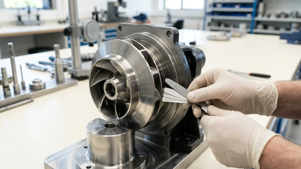
Phase 3: Precision Wear Ring Metrology & Inside Micrometer Audit SOP
- Pump Teardown: Disassemble casing and pull rotating element in workshop.
- Diametrical Metrology:
- Measure casing wear ring inside diameter (D_casing) using a 3-point inside micrometer at 3 axial locations. - Measure impeller hub outside diameter (D_impeller) using an outside micrometer.
- Radial Clearance Calculation:
Phase 4: Lathe Machining & Stellite Wear Ring Fitting SOP
- Machining: Machine replacement casing wear ring from high-hardness metallurgy (SS410 / Duplex SS / Stellite).
- Clearance Setting: Machine bore to achieve exact 0.20 - 0.25 mm radial clearance conforming to ISO 5199 Table 1.
Phase 5: Dynamic Rotor Balancing to ISO 5199 Grade G2.5 SOP
- Dynamic Balancing: Mount refurbished impeller, shaft, and sleeve on dynamic balancing machine.
- Balance Certification: Achieve residual unbalance < 1.0 g\cdotmm/kg conforming to ISO 5199 Grade G2.5.
Phase 6: Laser Alignment, Flow Verification & Re-Commissioning SOP
- Laser Alignment: Align pump and motor shafts using dual-laser alignment tool (≤ 0.03 mm concentricity).
- Performance Verification: Restart pump; measure flow rate with ultrasonic meter; confirm actual flow matches factory curve within ± 2.0%.
6. Materials of Construction, Metallurgy & Wear Ring Hardness
Cast Carbon Steel & SS316 Casing Components
- Structural Housings: Cast Carbon Steel (WCB) and investment cast SS316 pump casings with precision-bored wear ring landing registers conforming to ISO 2858 dimensions.
High-Hardness Differential Wear Ring Pairs (ΔHB ≥ 50)
- Galling Prevention: To prevent explosive metal-to-metal galling during startup transients, API 610 mandates a minimum 50 Brinell (HB) hardness differential between stationary wear rings (e.g., SS410 hardened to 350 HB) and rotating impeller wear rings (SS316 / Duplex SS at 280 HB).
Monolithic Direct-Sintered Silicon Carbide (SSiC) Annular Rings
- Extreme Abrasive Duty: Monolithic direct-sintered SSiC ceramic wear rings providing extreme hardness (> 2500 HV) and zero abrasive wear in chemical slurry service.
Virgin PFA / Pure PTFE Linings for Zero Corrosion Slip
- Corrosion Resistance: Transfer-molded virgin PFA (3.5 - 5.0 mm) lined casings eliminate chemical leaching and corrosion pitting that widen internal clearances.
7. The Maintenance Engineer's Actual Flow Decision Matrix
Follow this structured engineering guide when diagnosing low flow rates in operating process pumps:
| Observed Flow Deficit (ΔQ) | Radial Clearance (c_radial) | Volumetric Efficiency (\eta_vol) | Recommended Maintenance Action |
|---|---|---|---|
| < 3% Deficit | 0.20 - 0.28 mm | > 96% (Normal) | Acceptable; continue routine monitoring |
| 4% - 8% Deficit | 0.30 - 0.40 mm | 90% - 94% (Moderate) | Plan wear ring renewal during next scheduled shutdown |
| 9% - 18% Deficit | 0.42 - 0.60 mm | 82% - 89% (High Slip) | Schedule workshop overhaul; machine new wear rings |
| > 20% Deficit | > 0.65 mm | < 80% (Severe Loss) | Immediate overhaul; inspect impeller for cavitation erosion |
8. Worked Gujarat Chemical, Textile & Industrial Plant Case Studies
Case 1: Vatva GIDC Chemical Synthesis Reactor Pump Slip Loss Fix
- Plant Context: A specialty organic chemical intermediate plant in Vatva GIDC operating a 120 m³/h, 42 m head sulfuric acid transfer pump.
- Problem: Delivered flow dropped to 94.5 m³/h (21.2% deficit), extending reactor charging time from 45 minutes to 72 minutes.
- Root Cause: Abrasive iron sulfate particles had abraded the casing wear ring, expanding radial clearance from 0.22 mm to 0.72 mm (Q_slip increased from 4.8 m³/h to 26.1 m³/h).
- Action Plan: Teflow Pumps engineering team:
- Disassembled pump in our Ahmedabad workshop. - Machined a replacement wear ring from hardened Duplex SS 2205 with a Stellite face (380 HB). - Restored radial clearance to 0.22 mm and dynamically balanced rotor to ISO 5199 Grade G2.5.
- Outcome: Delivered flow rate restored to 121.2 m³/h; reactor charging time dropped back to 44 minutes; saved over 3.4 lakh INR in monthly production delays.
Case 2: Narol Continuous Textile Stenter Caustic Pump Actual Flow Recovery
- Plant Context: A textile dyeing and printing mill in Narol operating a caustic soda circulation pump (80 m³/h, 28 m).
- Problem: Caustic circulation flow dropped to 64 m³/h, causing uneven fabric mercerization.
- Action Plan: Overhauled pump casing, installed precision SS316 wear rings, and dressed impeller vane tips.
- Outcome: Flow restored to 81.5 m³/h; fabric quality defects eliminated.
Case 3: Odhav Effluent Treatment Plant Centrifugal Pump Slip Overhaul
- Plant Context: An industrial CETP in Odhav pumping treated wastewater (150 m³/h, 35 m).
- Problem: Motor drew full 22 kW load but delivered only 118 m³/h due to extreme wear ring erosion.
- Action Plan: Installed monolithic SSiC ceramic wear rings with 0.20 mm radial clearance.
- Outcome: Flow increased to 152 m³/h; motor power consumption dropped by 3.2 kW (2.1 lakh INR/year electricity saving).
Case 4: Surat Synthetic Dye Transfer Pump Volumetric Efficiency Restoration
- Plant Context: A synthetic dye manufacturer in Surat transferring liquid dye slurry.
- Problem: Abrasive dye pigments enlarged impeller clearances, dropping volumetric efficiency to 76%.
- Action Plan: Replaced casing wear ring and applied hard ceramic coating to impeller shroud.
- Outcome: Volumetric efficiency restored to 96%; flow restored to full rated capacity.
Case 5: Ankleshwar GIDC Pharma Intermediate Solvent Slip Remediation
- Plant Context: A pharmaceutical bulk drug plant in Ankleshwar GIDC operating a sanitary solvent pump.
- Problem: Solvent recirculation through worn gap caused fluid temperature to rise 8°C, threatening solvent flashpoint limits.
- Action Plan: Restored OEM clearances with virgin PTFE wear rings.
- Outcome: Temperature rise dropped to < 1.2°C; solvent safety compliance restored.
Case 6: Dahej PCPIR Petrochemical Acid Transfer Flow Loss Overhaul
- Plant Context: A petrochemical facility in Dahej PCPIR operating high-flow nitric acid transfer pumps (250 m³/h).
- Problem: Nitric acid corrosion widened wear ring clearances, causing 42 m³/h internal slip loss.
- Action Plan: Replaced internals with PFA-lined casing inserts and Hastelloy C-276 wear rings.
- Outcome: Flow restored to 252 m³/h; maintenance interval extended to 36 months.
9. Comprehensive Master Actual Flow Verification Checklist
Execute this metrology and clearance verification protocol during pump overhauls:
Actual Flow Rate & Wear Ring Metrology Verification Protocol
10. Summary & Specialized Flow Metrology Services in Gujarat & India
Calculating and optimizing actual pump flow rates—mastering internal annular slip fluid mechanics, measuring radial wear ring clearances, auditing field ultrasonic flow rates, eliminating internal recirculation losses, and dynamically balancing rotating assemblies to ISO 5199 Grade G2.5 across Vatva GIDC, Narol, Odhav, Surat, Ankleshwar, and Dahej—conforming to ISO 5199, ISO 2858, and DIN 24255 standards—is the proven engineering standard for process plant efficiency and uptime.
Partnering directly with an established Gujarat rotating machinery manufacturer provides chemical plant maintenance engineers, reliability leads, and rotating equipment specialists with immediate technical access to on-site flow metrology teams, transit-time ultrasonic flow meters, precision wear ring machining workshops, dynamic balancing facilities, and genuine spares dispatched directly from our Ahmedabad factory. Our technical engineers provide emergency on-site troubleshooting, turnkey pump overhauls, and complete volumetric efficiency restorations.
Teflow Pumps operates a specialized industrial machinery manufacturing and service facility in Ahmedabad, providing emergency centrifugal pump overhauls, precision wear ring lathe machining, Stellite hardfacing, dynamic balancing, laser alignment, and genuine rotating equipment spares across Gujarat and India conforming to ISO 5199, ISO 2858, DIN 24255, and IS 5120 standards.
- Direct Technical & Emergency Helpline: +91 98251 62709
- WhatsApp Technical Desk: Share measured field flow rates (Q_m³/h), operating pressure readings (bar), chemical fluid names, pump nameplate photos, or flow loss symptoms to wa.me/919825162709 for immediate technical review, slip loss calculation, and formal quotation.
- Request an On-Site Pump Flow Audit & Wear Ring Metrology: Contact our senior rotating equipment engineers for emergency plant surveys, wear ring overhaul proposals, and formal quotation. Our engineering team conducts comprehensive thermal evaluations, verifies ISO 5199 criteria, provides precision on-site or workshop reconditioning, and dynamically balances overhauled hot oil pumps to ensure maximum uptime across Gujarat's textile and chemical processing mills. We provide rapid technical evaluations, on-site plant surveys, and formal quotes.